Minipulse
We met a guy in Beechworth travelling with his family while camping. He came over to borrow some tea and while talking mentioned that he did a bit of prospecting. "As in gold?" we asked, interested. Beechworth is part of Victoria's "golden triangle" and our campground was on a flat below a hillside full of old mining shafts. "Sure" he said, and pulled out a glass tube with at least an ounce of gold in small nuggets rattling around. I guessed it was worth about US$1600... And all you need to find it is a $5000 metal detector, or $10000 for a really good one. I was prepared to spend about $200 for a new camping toy and so this project was started.
The Kit
Searching around I found several forums full of DIY detector builds - the Geotech forum is the one I spent most time on. There is an active community of builders and it didn't seem too hard. I settled on the Minipulse kit, from the DiyDetector shop - reasonably priced at £34.00. It was delivered in around ten days. Here's what arrived.

Right away I worried about the ICs - all rattling around in one bag, surely the pins would be bent? At the very least I'd be buying new sockets.


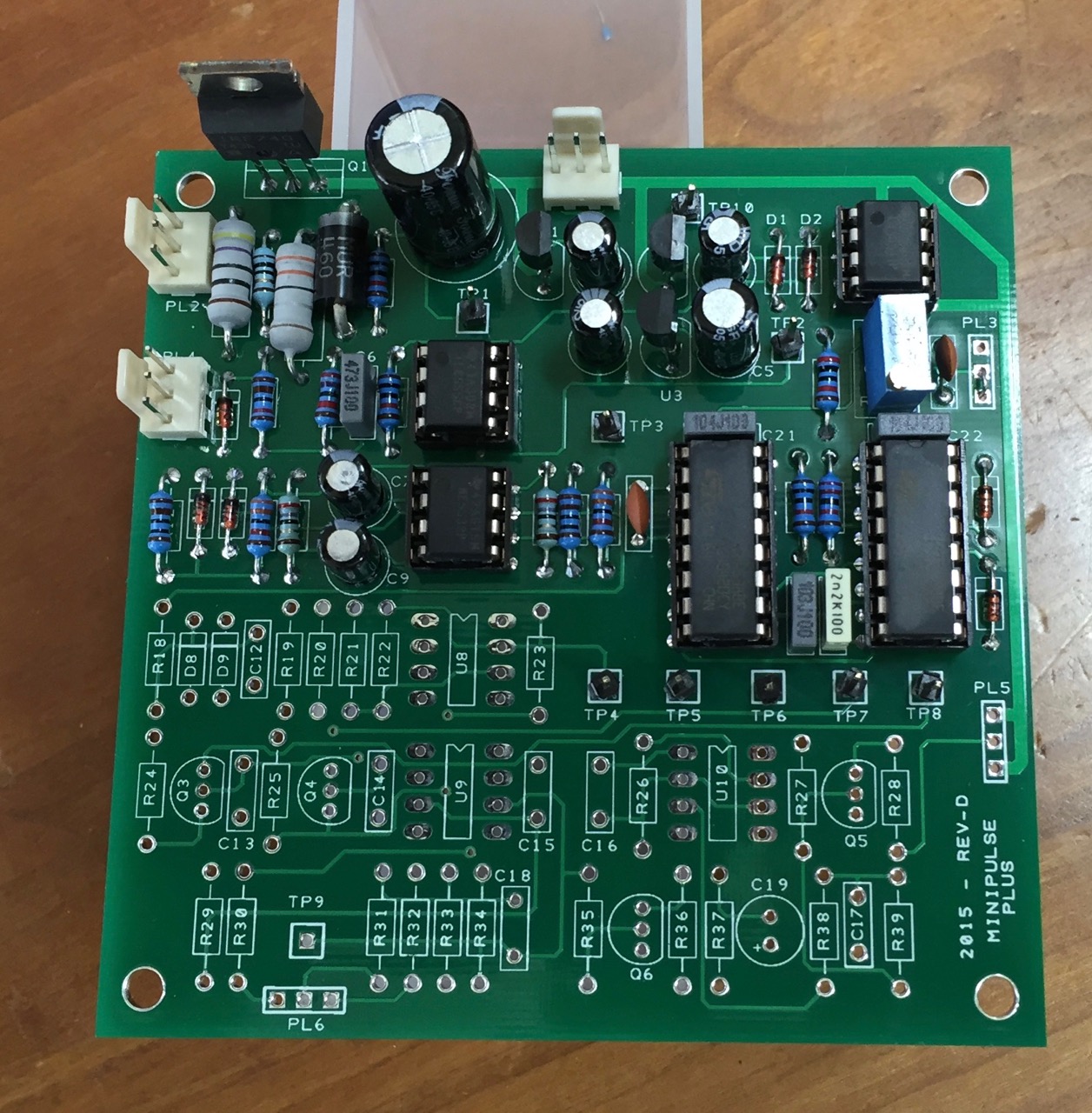
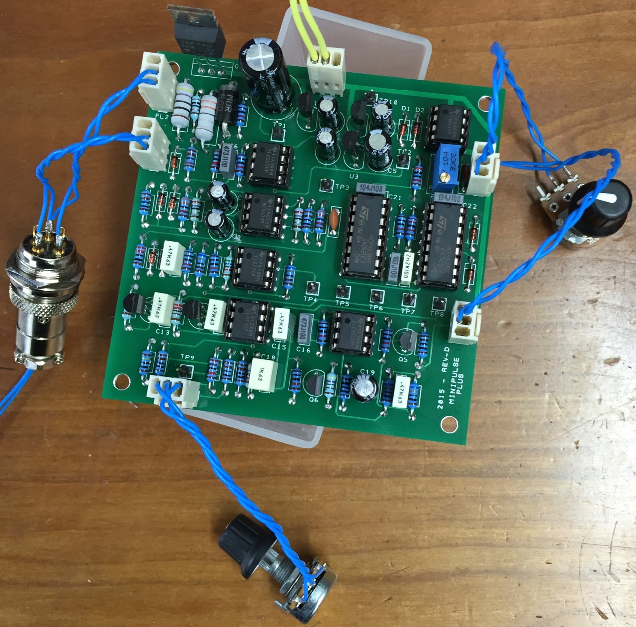
The PCB is a quality item. Holes plated through, flowed ground plane, heavy fibreglass substrate.

And here are all the parts in a bit more order. I was going to separate them into small containers by construction step (there are 9 steps) but I found it just as easy to take them from this mat as each step was complete.
The electrolytics are decidedly cheap, nasty-looking things - brand names like "Forever" and "Suntan". I'm not looking for audiophile stuff like Black Gate or Cerafine but I have replaced too many bulging, leaky electrolytics in the past ten years. Anyway I used them. That's about the only complaint I have about the parts. You can see from the individually labelled resistors that silverdog has gone to a lot of trouble to make this as easy as possible to put together right.
The instruction manual is available before you buy the kit so you can see what you'll be building. The manual stresses that you should follow the build steps in order and perform the tests at the end of each step. This post describes following those steps and shows the result of each test.
I have one very tiny criticism (in steps 7 and 8) but otherwise it's very, very good. Up front I'll say this is a great kit. Buy with confidence.
Step 1
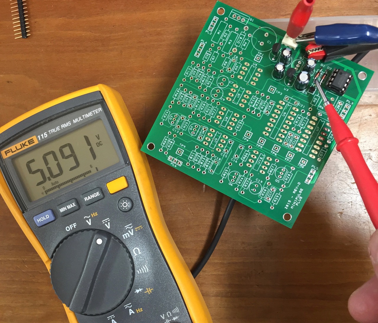
The first step is an easy one, getting a 5V supply using a 79L05. I confused myself by looking for a TO220 package before realising it was a TO-92. That done, an easy step.
Step 2
Another easy step! This thing will be done in no time. A 78L05 provides +5V.
Step 3
Now starts the analogue stuff so I'm out of my comfort zone. I picked up a 470nF capacitor instead of the 47nF here, my only component mistake - I just don't do enough electronics to read "473J100" without having to stop and think. When that was fixed the test showed I was very close to the expected result - at least close enough to go on.


OK, something isn't exactly right. My pulse width appears to be ~45uS. I do have a higher supply voltage, 13.8V from a fixed supply intended to power a ham radio. I don't have an adjustable supply or any batteries to do an actual 12V supply. The frequency is OK, and it's in sync with the pulse from U2, so I think it's OK to go ahead.
The manual also suggests putting on headphones and listening for an induced noise when the coil is close. It works!
Update! Forum user teleno reported that switching out the TLC555 chips supplied in the kit for NE555 chips brings the pulse to 58uS. Good thing everyone has ten or so NE555s in the junk box. (Mine must be around 30 years old!) I now see around 54uS and I'm a lot happier with that result. If the TLC555 45uS pulse is OK, the kit manual needs to be updated to say so.

Step 4
My coil inductance is 370uH, or at least to the degree that my very cheap Mastech MY6243 LCR Digital Multimeter, Capacitance and Inductance Tester can measure it. (I bought it just for this project - usually I only do digital electronics, never anything with a coil!) On this basis I did not adjust the damping resistor but I might later.

That's a little high but once again I'm going with it and moving on.
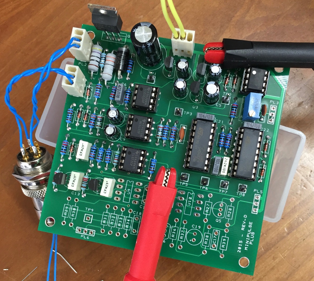
Step 5
OK, now it's time to hook up the coil since I need to measure voltages changing as a metallic object comes close to it. There is no conventional coil connector supplied with the kit but I would like to be able to use a commercial coil maybe, so I bought the pair of connectors. I wasn't sure about how to wire it up but the manual makes it clear. Did I mention this is a great kit?
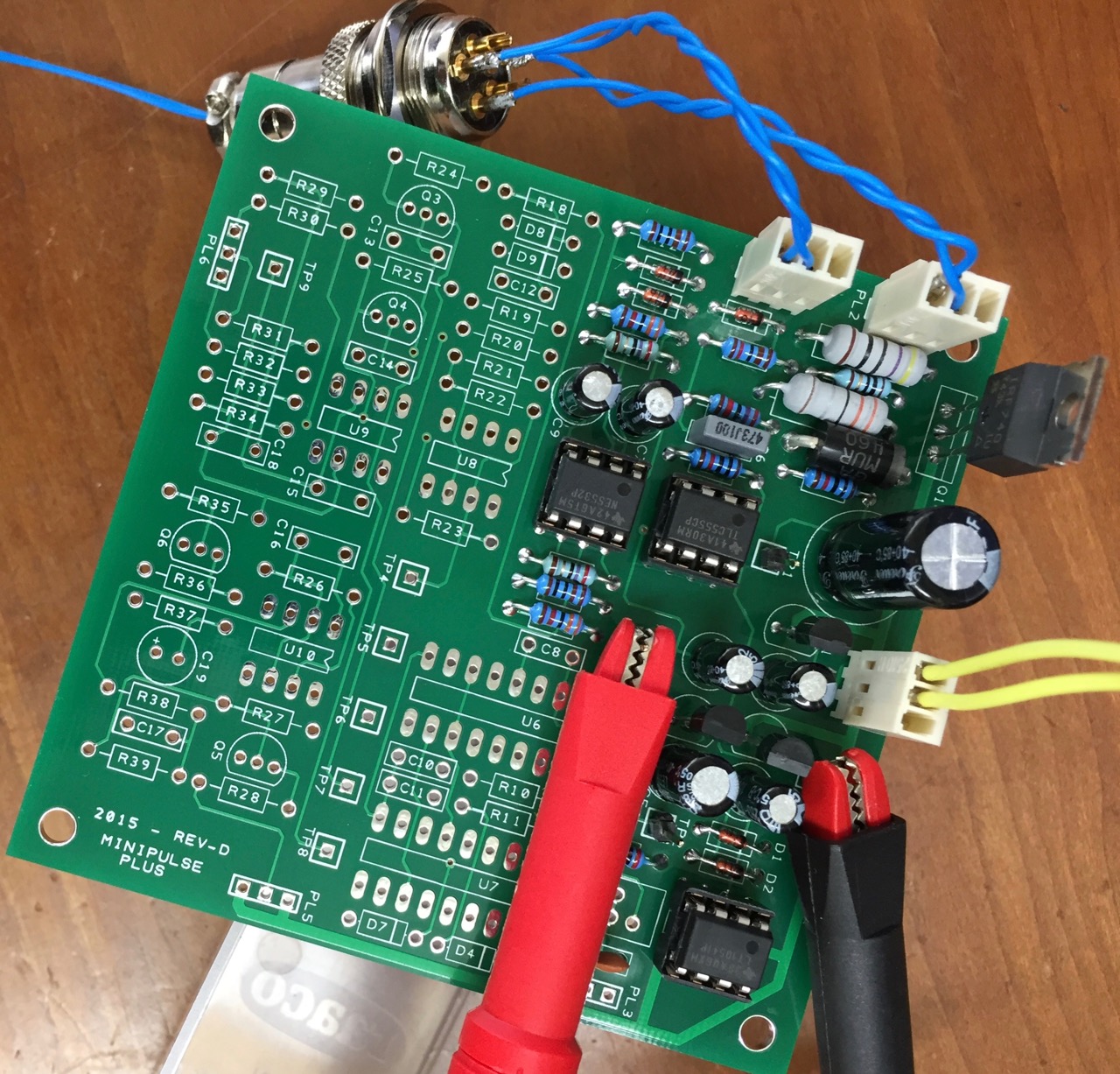
At this point some of the uneasiness from previous steps evaporated. Clearly something is working properly.
Step 6
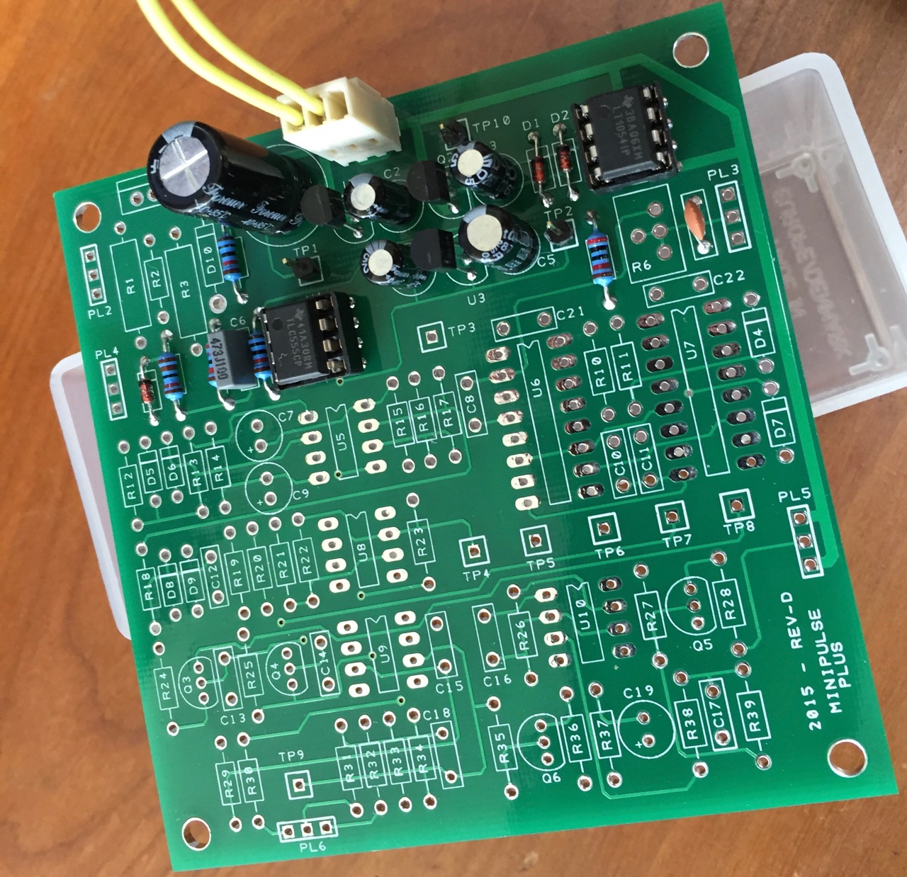
This step includes the two 16-pin devices, whose sockets were the most mangled from being stuck in the plastic bag with all the rest. They straightened out OK though. It is a thoughtful step to include sockets even for the cheap chips like the 555, they are easily destroyed with clumsy soldering and a pain to desolder. With the socket you can get the pins (almost) as hot as you like and not worry about pausing between pins.

Step 7
The section parts list says it's time to use the TL062 op-amp, but a TL072 is supplied. For all intensive porpoises that's the same thing, and the full parts list makes that clear but maybe it could be mentioned in the section parts list also?
The test in this step is about the opposite of the one in step 5 - this time the voltage at the test point goes up rather than down as the metallic object nears the coil.
Step 8
Just like in Step 7 the op-amp supplied is an equivalent, a TL071 instead of a TL061.
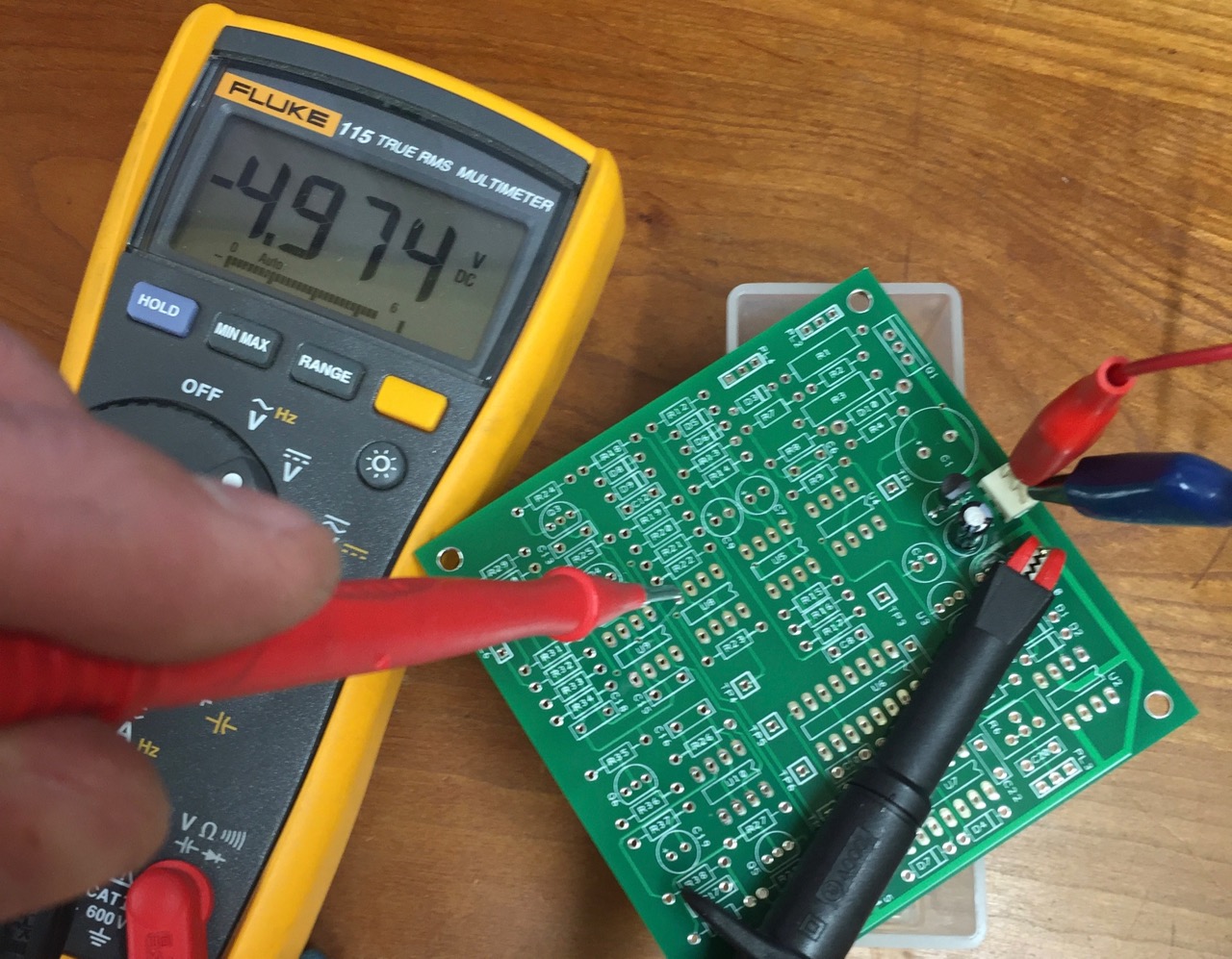
The test step here is a tricky adjustment to make on the oscilloscope, I would almost suggest doing it on the meter instead - the voltage you are watching dances around a bit and it is hard to get it at zero but it doesn't have to be exact.
I couldn't capture everything in this short clip so here's the explanation. The self-adjusting threshold causes the voltage at TP9 to adjust back to 0 in the absence of a moving target. The display here shows the voltage as a target (the big acetone can from previous clips) moves close to the coil, pauses and then moves away. All working!
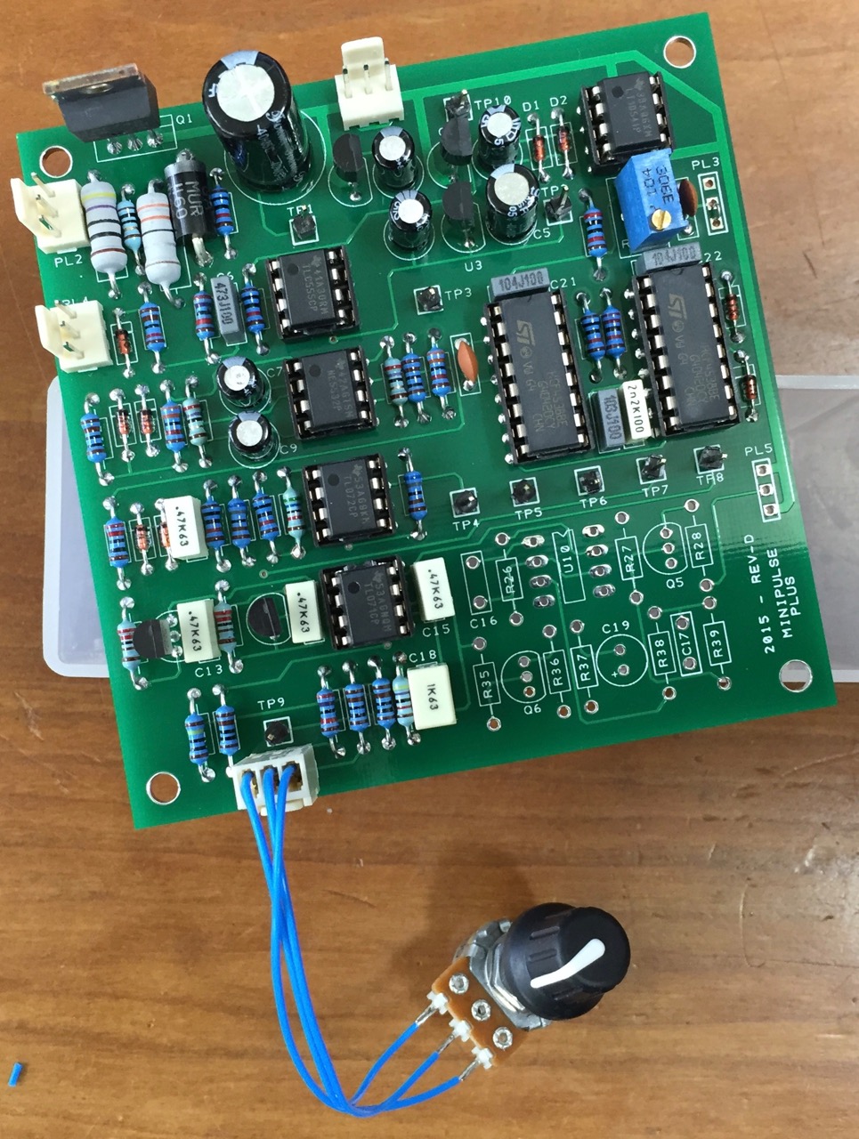
Step 9
Oh wow, that's a horrible sound from the included mini-speaker. I guess when the sound indicates that you've found something it's much more welcome. Anyway - it works! Obviously there is more tweaking to do and I need to go back and look at the scope, but that's a wrap. It detects metal.
Conclusion
Building this kit is going to take around three hours at an absolute minimum and you should probably budget more like a whole day if you are not very experienced. I took around five hours in all, including winding the coil (and many more 3D printing a coil former, but that's another story). If you have only ever made LEDs flash with an Arduino this might be too much for you, but then again if you go slow and ask questions in the forum it can probably be done. Just be cautious and don't guess.
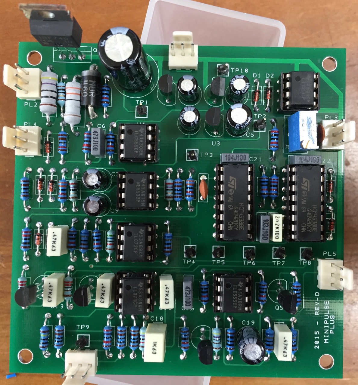
After building the whole thing I have one more complaint about the PCB - the holes for the resistors are often far too large. When you put the component into the holes and bend the leads a little they just rattle around. It looks like a uniform hole size was used for all of the resistors, a comfortable fit for the 2W units but less so for the 1/4W, which are the majority.
I'm pretty happy to have a metal detector, especially one so cheap! But there's still a long way to go before it can go in the car and find some gold. I need to do a lot of work putting it in a case and building the head cover, hand grip, making a battery system etc. More posts to come...