Amiga 1200 Keyboard, part 2
Deriving the circuit.
Lots of people make keyboards these days. It's not even a big thing; once you know your circuit you get a board made, buy switches, use an open-source controller to send USB HID keystrokes and you're done. So why not? I decided to dive right in.
First up, what software to use? In the past I have used Protel/Altium for various things; one thing I used it for a long time ago was the Mac mini drive adapter. Designed to connect a 3.5" hard drive to the original G4 Mac mini where it expected a 2.5" hard drive, it was pretty successful.
This was a big deal at the time because 2.5" drives were not only usually slower, they were usually a lot smaller - and a lot more expensive. Existing adapters could connect a drive physically but would reverse the pins. Amusingly I once connected a 2.5" hard drive in reverse and a piece of silicon detached itself from the drive PCB with a loud bang and a smoke trail. Don't do that.
Anyway, off to KiCAD. Things aren't as polished as you might wish - for example the Mac version I started with used white text on a light gray background - but it works really well. So probably I won't bother looking at the commercial solutions again, for the kind of work I do KiCAD is plenty.
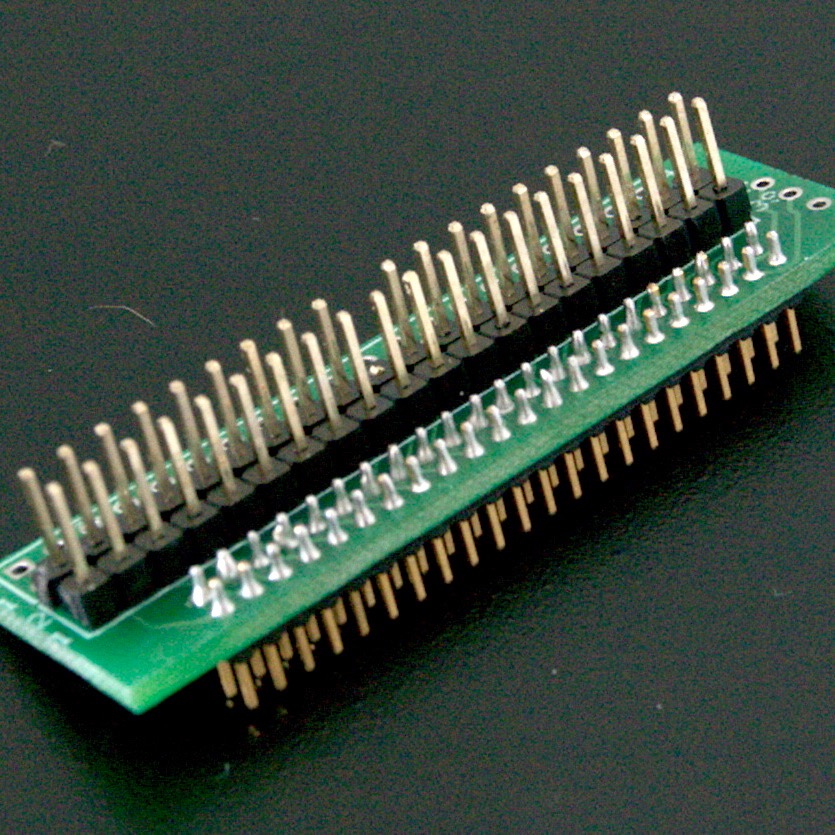
To the schematic! How to design an Amiga keyboard? Well it's a membrane, and it connect to the mainboard by a flexible cable. There's no circuitry on the board, only a LED. So maybe I should make just a passive matrix and get it connected so that it looks just like the original, make a simple Amiga 1200 replacement? Which would mean extracting the circuit for the original keyboard. So I took the membrane out, pictured in the previous update.
The guy that made this membrane had fairly primitive CAD compared to today. Maybe it was even done by applying opaque tape to a transparency to produce artwork at double or even higher magnification, then reduced down to actual size? Anyway considering that I didn't feel too bad about deriving the circuit by tracing even if it had me dreaming of parallel lines. A light table would have been nice but a white piece of paper behind on a sunny day was enough.

Yes, there are documents that describe the keyboard circuit. However making a PCB is kind of a permanent thing, you want to be sure before you enter your credit card details. So I decided the ribbon connector that goes to the A1200 mainboard would be numbered arbitrarily from left to right, giving pins 1 to 31. Each pin would connect from 1 to n other places. By writing a number in a box on this diagram I made I would come up with a map of connections of every key (and LED) in the matrix.
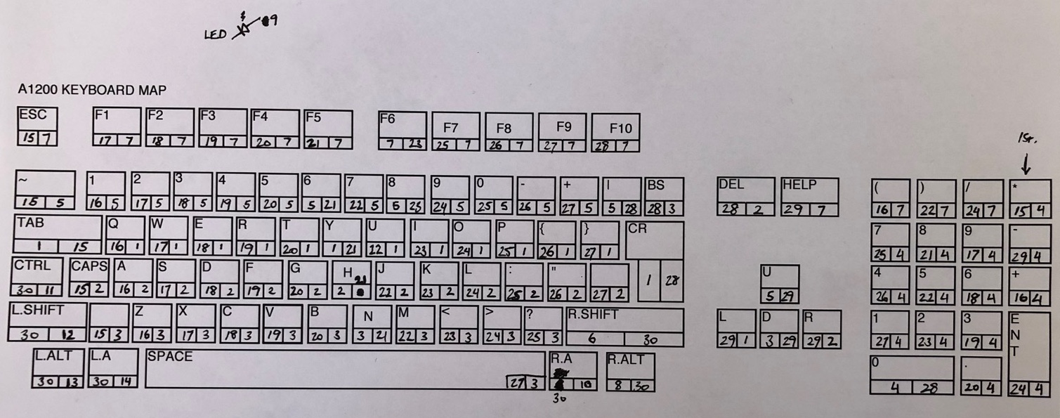
And that's the whole circuit.
A long time ago a grumpy old electrical engineer told me Protel for Windows was worthless because it didn't use netlists. I'm not sure how right he was, but I believe in netlists. By writing down just what lines are connected to what key contacts you get a netlist - a list of pins that must be electrically connected together. From there it's just a matter of entering this information into KiCAD, and making sure that when you extract a netlist from the schematic you have drawn, it describes the same electrical connections. Going through the netlist net by net ensures that everything is as you want it to be, not missing a connection because you were one pixel off here or there when drawing lines in the schematic editor.