Amiga 1200 Keyboard, part 6
Fitting the PCB
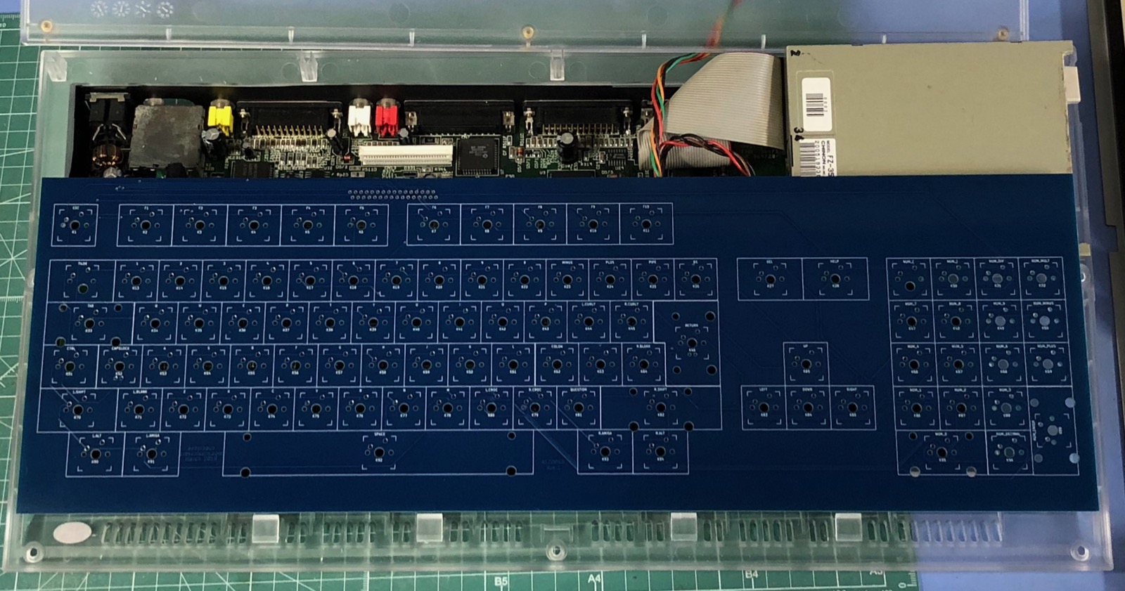
The PCB is back! It's really big, barely goes in my backpack with the zip shut. I can get a 104-key modern board in my backpack but not this PCB! It arrived right on time and very carefully packed. This is a simple board so the difficulty rating is pretty low but the manufacturer really has done a great job and I would not hesitate to use them again.
Does it work?
Building it was easy. The PCB-mount switches stuffed in easily and so did the FFC connector and LED. It works! With DiagROM in the system I tried it out and every key generates the right codes, except for Help and Del. This was my fault - I forgot to solder those two switches! But everything is fine, right down to the Caps Lock LED turning on and off.
Does it fit?
No. I kind of expected to find a few things that needed fixing and I did. This is what comes of not having a piece of 2mm material to fit in place and see where the problems might be before having a PCB made.
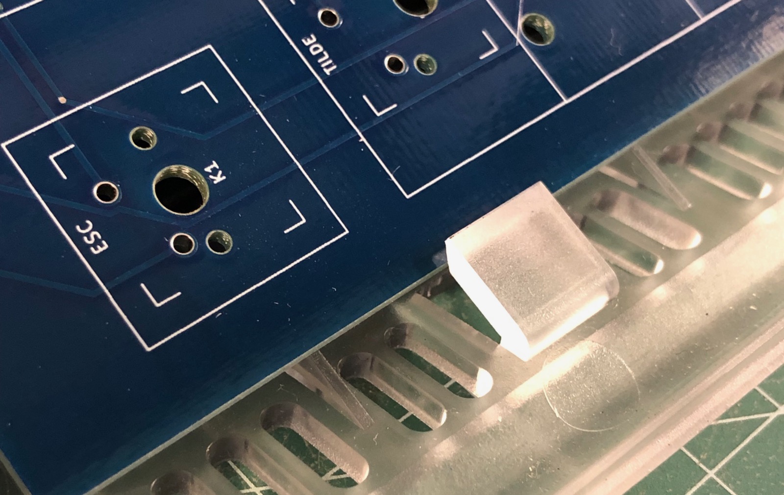
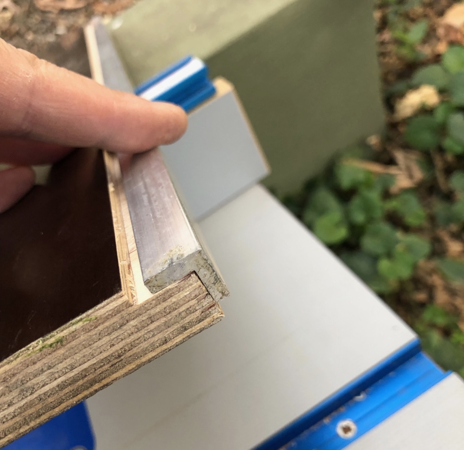
- Too high! The board sits perfectly across the width of the case, right on the thin ledges provided in the bottom case mold. Unfortunately in this position the keyswitches sit up too high.
- Too thick! The PCB material is too thick to fit under the clips at the front of the Amiga case. That's OK, I can route it back and add a strip of metal attached to the front of the PCB that will fit. As mentioned it is too high anyway.
- No LED window! The A1200 case has a small PCB with three LEDs in it. The original keyboard has a hole cut out to allow the lid to close. I overlooked this.
- Flexy! This will definitely require aluminium angle at the top edge to stop the flex, as expected.
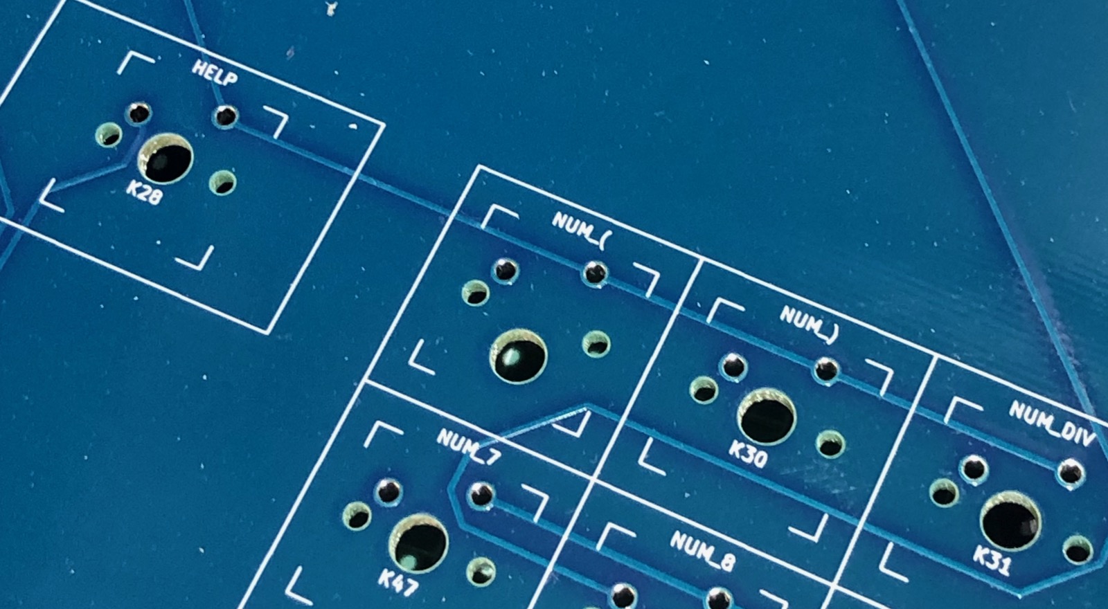
- WTF? Check out the weird footprint below - this happened with the TAB key and the numpad '(' - both keys on the top left of a group. Both showed that they had the right footprint in KiCAD. Both corrected instantly as soon as I selected the footprint again, while making rev 2. You can see the central pin for the keyswitch has moved down. Easily fixed with a round file but I would rather it is in the right place.
Though I want the stiffness of 2mm PCB material here it's too thick to go in the clips at the bottom of the case. I will need to cut the board back and attach a piece of 1mm aluminium, stepped down to the level of the clips.
And the keycaps sit too high when the PCB is sitting on top of the case supports. The entire PCB needs to be lowered within the case.
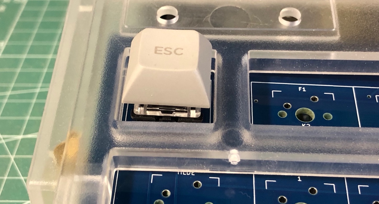
Make it fit - lower It
Sitting up on the supports makes the keys too high. The only thing to do is trim the edge of the board so that it can drop down inside the case, below the supports, but still be supported somehow. There is room for screws and brackets if careful. Is there an aluminium extrusion somewhere that could do this? A quick search produced no joy, at one end Bunnings with a lot of standard and chunky extrusions that don't look useful and at the other end a lot of industrial suppliers that can probably do anything but say "call us for a quote". Small quantities of unusual angle could easily cost more than my whole project, so I gave that up.
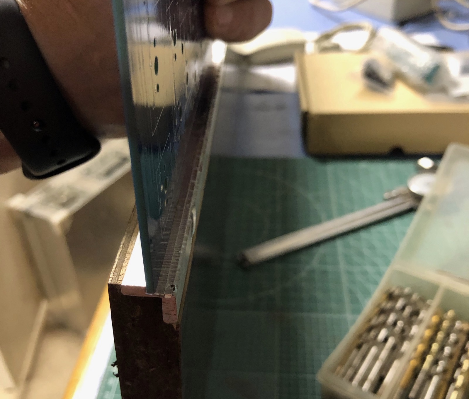
Then I thought about routing some aluminium. For a Mac mini project some time ago I routed a CD slot in a sheet of aluminium. It does dull your router bits but if everything is well supported and you are careful, no problem. (That's what using a router is really - 95% preparation, 5% cutting.) If I took some 3mm thick right angle and routed in from the outside corner I could create a step-shaped piece that would sit on the case ledge, then drop down to support the keyboard. The height this drops the keyboard by would be controlled by the depth of the cut with any excess trimmed off the top so the case can close. With 3mm of thickness, that allows for 2mm siting on the ledge (plenty) and 1mm of material left to support the keyboard (plenty). I did not like the idea of putting my fingers 10mm from a spinning router bit so I first made a rebate along the edge of a piece of thick ply then placed the angle wrapping around the timber with one face in the rebate. Then attached with screws through the face that won't be routed, so that the face that will be routed is exposed and securely fixed.
Then gradually increasing the size of the cut I added in a new rebate to the outside of the extrusion so that with the PCB resting inside the original angle, the new cut would sit on top of the original case keyboard supports. This picture shows the PCB sitting in the new cut, where the case supports will go. Later I trimmed off the excess height you can see above the PCB.
While this works, obviously I need a 3D printer. It would have been much easier and much quicker to design something to the exact dimensions required and then print it. I spent hours thinking about how to safely route this thin extrusion, then more time measuring and setting up the router for the cut. I don't need the side supports to span any distance or to prevent any flex, just not collapse so printed ABS or similar would have been perfect.
Having done as much as I could with rev 1 I was reasonably happy. I did not expect to get everything right first time. Time for rev 2!
The Changes:
- The F-row and the main body are too close together. I don't know how that happened but after a careful measurement that is fixed. I printed the artwork on A4 paper, carefully stuck it together and then made a test fit board with the paper showing key position. The next board should be spot on.
- The positioning of the FFC connector at the top of the board is too close to the edge, requiring cuts to a piece of angle aluminium if I am to use one for stiffness at the top of the board. Moving it down between the F-row and the main body of keys will fix that and might even make it easier to route.
- A large rectangular route is added so the existing LED PCB will fit as it did in the original keyboard.
- reduce the size of the board to allow for the aluminium angle so there should be no need to shave off the edge of the rev 2 PCB with the router.
- Added holes around the board to attach the mounting rails and the top brace/bottom piece.
- Added a 9U space bar on top of the 7U space bar so if one becomes available it will fit in just by moving the stabilizers.
- Changed to blue MX switches, they will sound great here and it's not like I will be using this keyboard in an office where people will complain.
- Changed to a black PCB finish.
Electrically these are no change. I re-routed the board with the changes above and came up with something very much like the first PCB, only with more vias. As mentioned I concentrated on making tracks on one side run vertically and tracks on the other side run horizontally. It's nice to do a two-layer board with no vias at all but getting rid of the last one might cost you hours of rework - so when it costs no more it is worth it?