Amiga floppy drive connector
Making a connector (I probably didn't need to make)
In between the Mac screen stuff going on I have some other projects happening. I'm in the middle of a ReAmiga 1200 build and when the very last chip I needed arrived I made some progress. Which is me all over, I would much rather be building physical things than writing code most of the time. Progress was stopped by a faulty Paula chip but I got thinking about the new machine's storage.
The ReAmiga allows floppy drive swapping on the mainboard, so an external drive can be DF0: - removing the internal floppy and adding an internal power supply wouldn't reduce compatibility at all. I really like the Goex from Centuriontech.eu and decided to make it externally housed with a better control knob and display panel (that's another story). What you can't get easily in 2021 is the 23-pin male DSUB connector.
The 23-pin version of these connectors appears to have been more or less a Commodore whim just as the 19-pin was Apple's. Nobody knows about them today - most manufacturers don't even show them as obsolete products, while the 25-pin style is plentiful and still available. I heard about someone having a small quantity manufactured in the last few years but originals are no longer to be found at a sane price, I saw one listed for over $800 on eBay last week. No doubt the seller hoping someone was that desparate...
(Could I have found one connector, under $10, if I looked hard enough? Of course! But I like making things.)
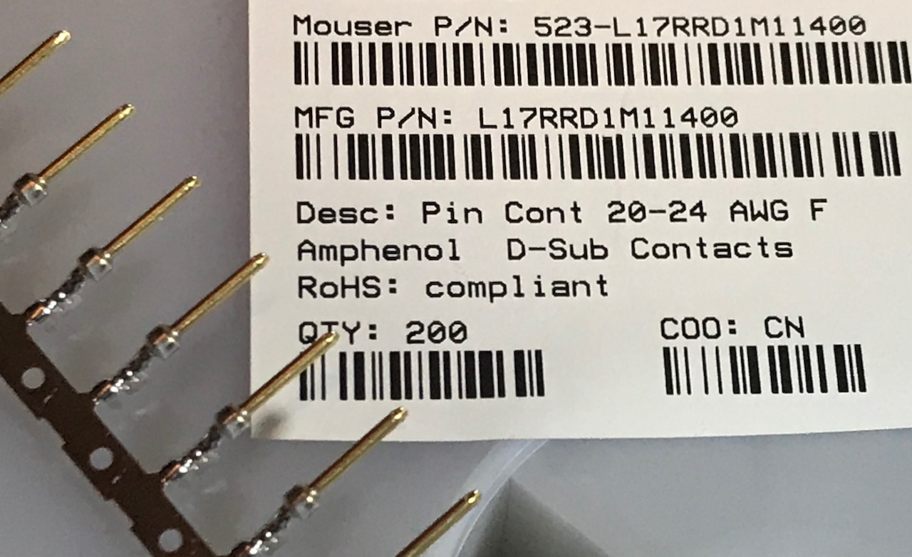
I bought some pins from Mouser and 3D printed some designs to try and make my own and discovered that these things need some really fine tolerances to fit and work. Initial plans to print a one piece front didn't work because the printer isn't quite accurate enough. Forget about putting numbers near every pin like the old ones used to have - I used a triangle marker near pin 1 but it is near impossible to see. In the design program it is easy to forget just how small these thngs are, then in the slicer realise that a feature that is just five layers high isn't going to come out as you hoped.
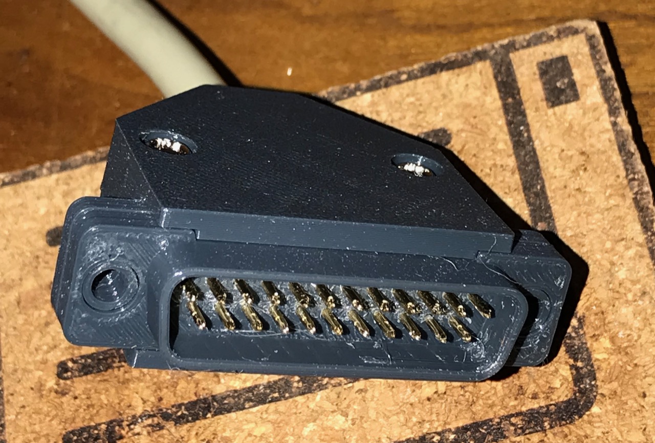
After a few iterations I had a rear part with a rear hole size that allowed the crimped part of the pin to pass through but not the barrel. I also made a front part that would accept the pins and hold them correctly in the trapezoid pattern, behind a shroud like the original plug. I had to mess with that front part a little - chamfering the holes where the pins insert was a good idea to aid insertion but too much chamfer allowed the barrels to be pulled forward out of the rear part, leaving pins staggered after removal. Eventually I arrived at chamfer dimensions that hold the barrel steady and help get all the pins inserted. Drilling out the front printed holes with a 1mm drill bit in a pin vise made it much easier to get the pins through.
Originally I decided to try a friction fit where the widest part of the pin ("barrel"), above the pin itself, would fit so tightly into the printed housing that it would not come out when inserted and removed from a socket. This wasn't a terrible plan but getting the pins fitted required a lot of force and after a few bent pins it clearly wasn't going to be a reliable method. Then I decided to try the split front approach on the basis that the barrel was still the largest part of the pin and could be sandwiched between the two parts.
(Maybe there are pins that would have been easier to design for, I did not find them.)

The wires thread through the back printed assembly. Know your crimper - mine is an Engineer PA-20. Get the connector in exactly the right spot in the tool and the wire fully inserted before crimping or the pin bends like a banana.

Once crimped, the wire and pin pass back though the holes and the barrel is seated.
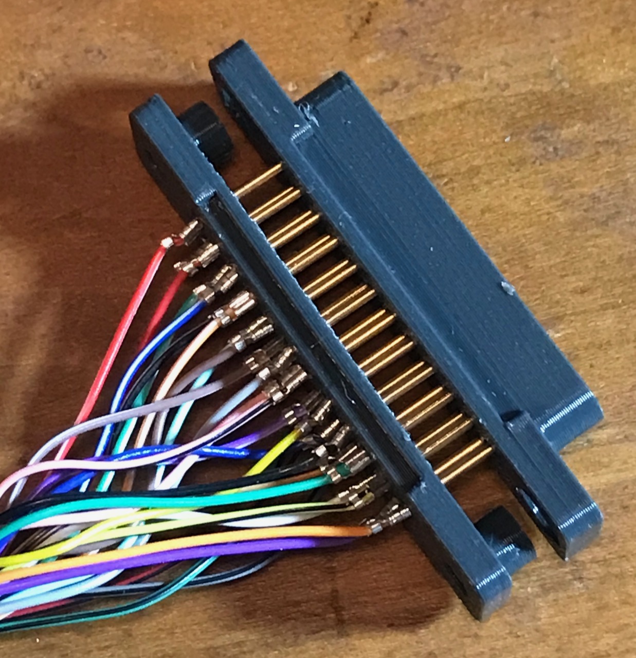
The pins all need to be inserted through the front printed part. Chamfers around the tops of the holes help to align but there is a fair bit of friction here. Best to put the shroud facing down on a flat surface and push gently down once sure the pins are aligned in the holes.
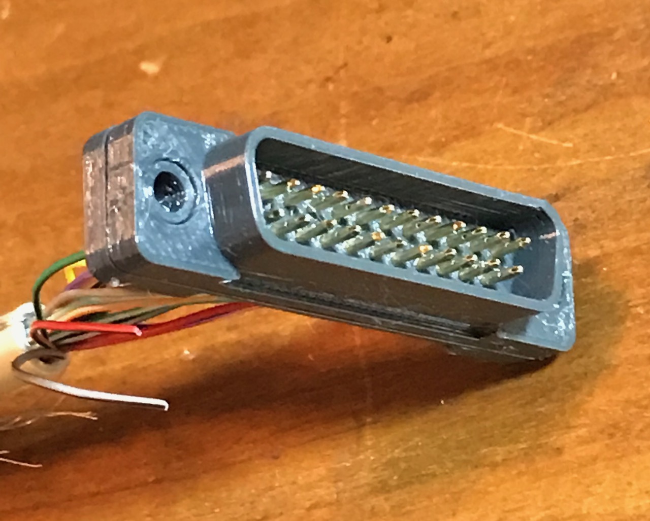
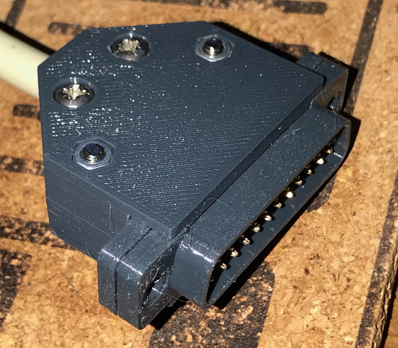
Once together the two pieces are held together by the shell ridges. The pins are held in place between the two pieces.
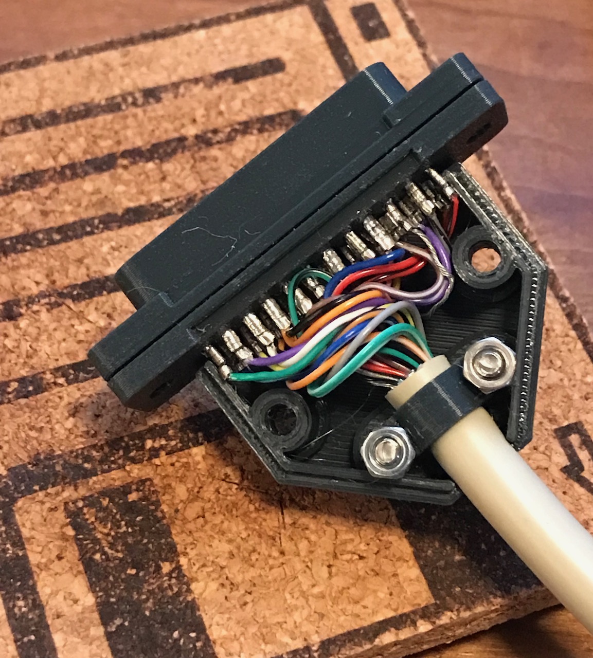
Functionally complete, next thing was to make it robust. I made a shell that uses two ridges top and bottom (four total) to retain the front and back pin assembly in the joined position. The final step was a cable clamp to make sure insertion and removal does not tug any of the wires out of its pin.
Doing this made it obvious why we now use USB for nearly everything, so many wires! I was lucky to have picked up a 20 metre cable someone was throwing out, this 25-conductor stuff is expensive if you can even find it.
(Thanks to the anonymous person that gave me the pictured cork floppy disk coaster, I use it constantly.)