Amiga 1200 LED assembly
I am not the first person to make a new A1200 LED board but it looked like a fun challenge and was something different - answering the question - can you print light pipes? This is for my ReAmiga 1.5. I have a roll of transparent Prusament PETG. When printed it comes out looking like an ice cube due to all the layer boundaries. The transparent A1200.net case I want to use means this transparent filament is a good match when making mounts for my keyboard and other parts.
While the A1200.net case is patterned on later model A1200 cases and uses 16mm rectangular holes for the LEDs, older A1200 cases used 15mm LED holes. If you look at my Printables page for this project you can find both versions of the clear pieces as well as the black base they slot into.
PCB manufacture was by JLCPCB. These days they are pushing the use of aluminium substrate, and selecting it added no cost to the job. I am not a fan of these boards. The edges are sharp and heat is sucked away from the place you are trying to solder. (Of course this is an advantage after soldering when there is too much heat in a design and the substrate can act as a heatsink.) It's also really sharp around the edges. I discovered a less-than-optimal feature in my original board and had a second batch made in conventional fibreglass.
[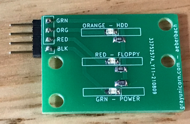](/images/2022-06-29-amiga-leds/bare-board-off.png)
Shipping is by far the most expensive part of this project. I'm using the most economical LEDs I could find on Mouser in 0805 size, the smallest I like to solder by hand. They drop 2.2V and have a maximum current of 20mA. I targeted 15mA and settled on a 186 ohm resistor.
[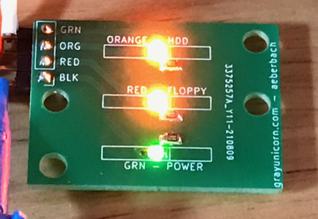](/images/2022-06-29-amiga-leds/bare-board-on.png)
Another thing I did was use a 4-pin right angled header instead of soldering wire direct to the PCB. Whenever I have removed an A1200 cover I have not liked the dangling wire. Sometimes I forget it's there and yank the wire. These wire connections break. Also I don't love soldering ordinary PVC-insulated wire to PCBs as the insulation melts and shrinks back. It would be nice to have rolls of PTFE-insulated cable in the right size and color at hand but that's expensive. Instead I made a cable connecting the 5-position mainboard end to the 4-position LED board end. Maybe I should have made it 5-position both ends? The colors are marked on the PCB silk screen.
[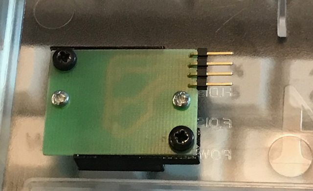](/images/2022-06-29-amiga-leds/reverse.png)
The design of the light pipes is the most interesting part of this project. The clear filament does look like a frosty ice cube when layer boundaries are involved. If the clear pieces are printed so that all of the layer boundaries are perpendicular to the desired direction of light then too much light is scattered by the time it reaches your eye. This makes the light blur more around the sides of the LED assembly and become less bright at the top. If the clear assembly is printed flat on the printer then the layers do deviate from what would be an ideal direction, from the LED to the visible part, but the transmission of light is vastly improved. I have not experimented with this idea but coating the vertical sides of the clear parts in an opaque paint might make the LEDS just a little clearer if no light is escaping the sides, and wrapping them in a reflective opaque material might make them marginally brighter? Simply extending the black light pipe housing part upward might achieve the goal of reducing light bleed.
[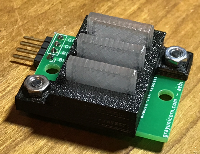](/images/2022-06-29-amiga-leds/assembled.png)
The datasheet for these LEDs will give the brightness output for a particular current. It would be possible to look at those curves and get a brightness output for each that is equivalent by varying the resistor value I suppose, but even then the subjective difference between orange and green might make them appear to output different levels. Here's the green by itself, which I think looks almost perfect:
[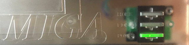](/images/2022-06-29-amiga-leds/in-clear-case-green-on.png)
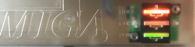
Here's the orange - noticeably brighter.
[](/images/2022-06-29-amiga-leds/in-clear-case-orange-on.png)
Next time I have everything apart I will try a slightly higher resistor value on the orange.