Amiga A1200 and A600 keyboards, version 2
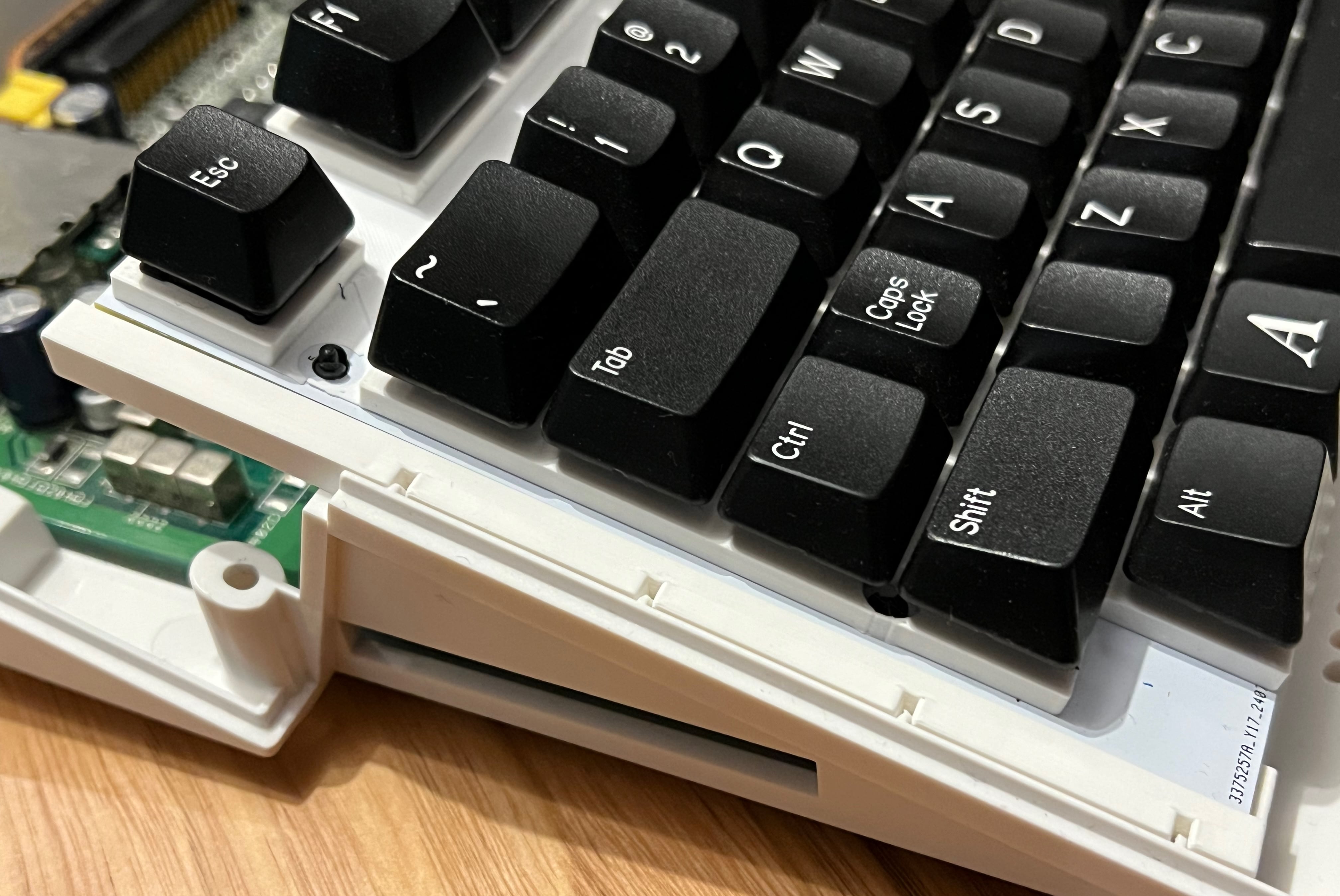
Some time ago I designed a replacement Amiga 1200 keyboard using MX keyswitches. Shortly after that I made one for the Amiga 600 also. They worked great, mostly. There were a couple of problems though: - MX key switches are taller than the original switch mechanism, so keycaps sit up too high - Amiga key caps with correct legend and size are really hard/expensive to get - Caps Lock key with a window to show the original LED is almost impossible to get - the mount I designed for the Amiga 1200 fitted badly
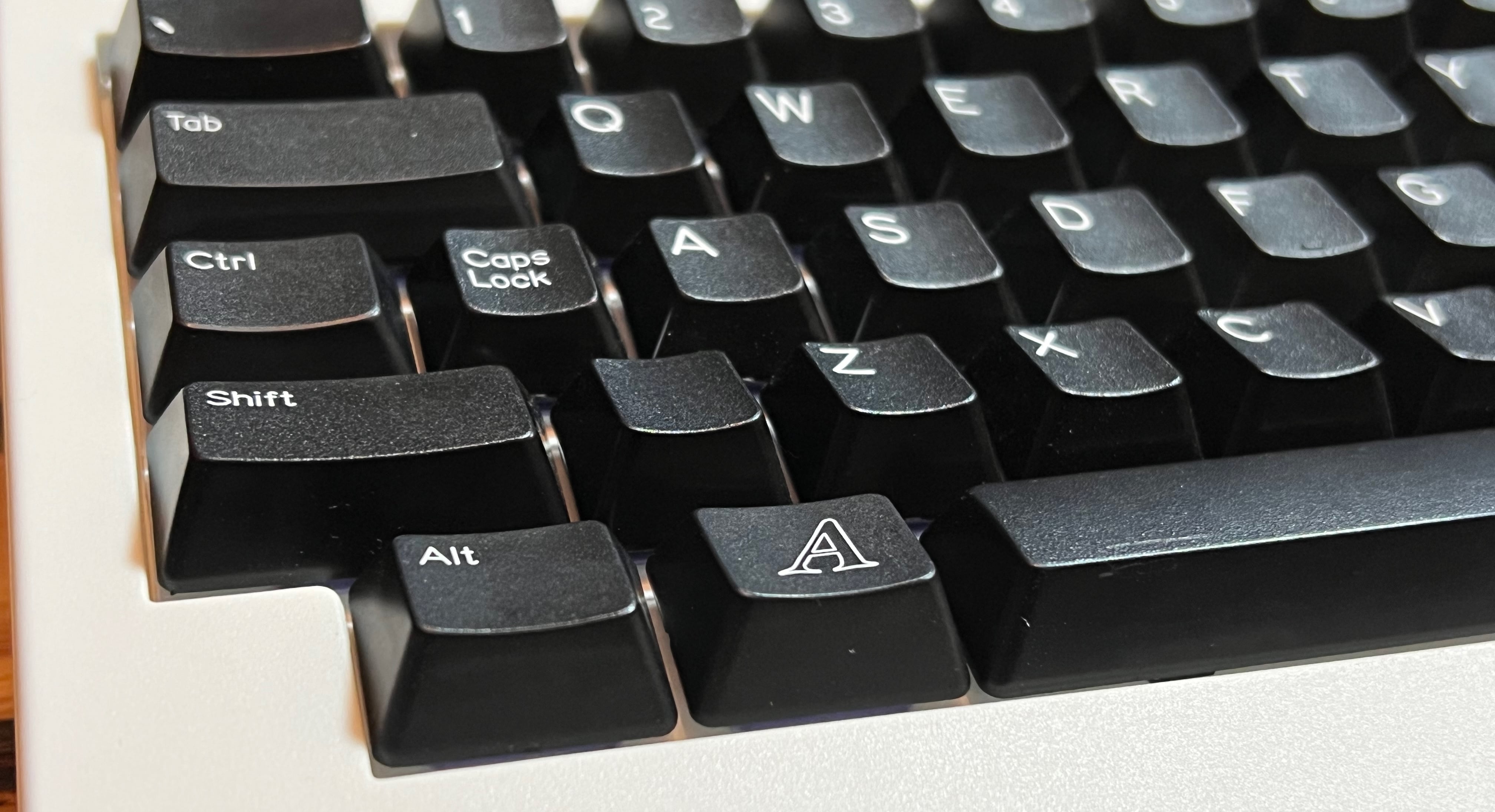
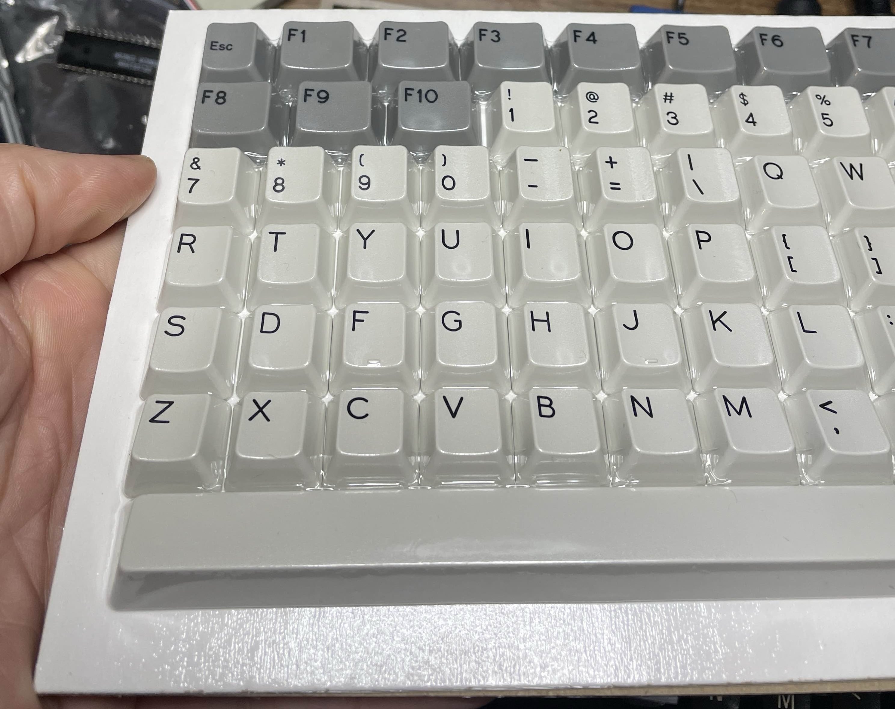
Then recently, Amibay user steveed solved the keycap problem, spending hours organising kits of Amiga-perfect keycaps from Signature Plastics. They are great! With these available I was inspired to redo the keyboards, without them I probably would not have.
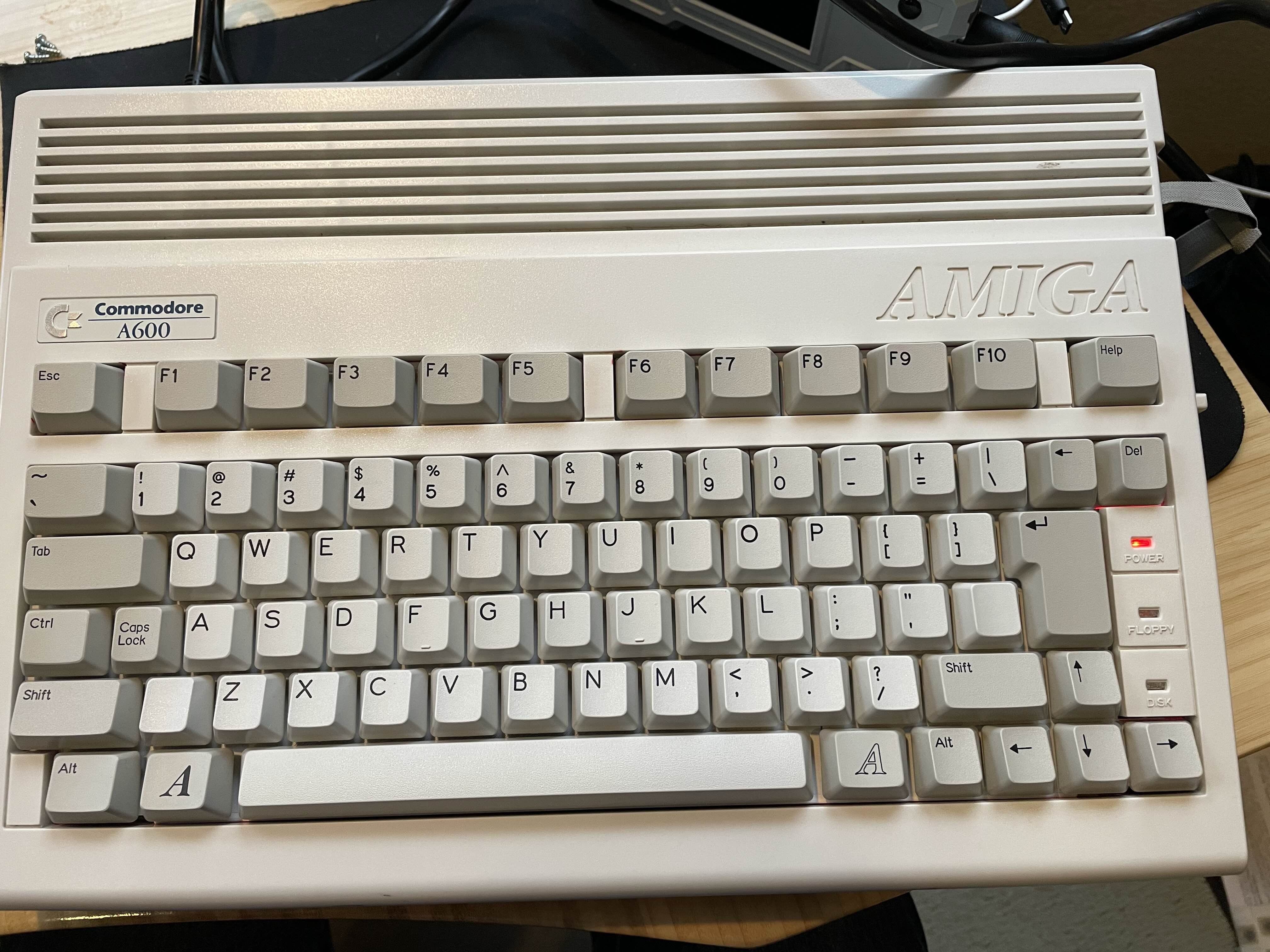
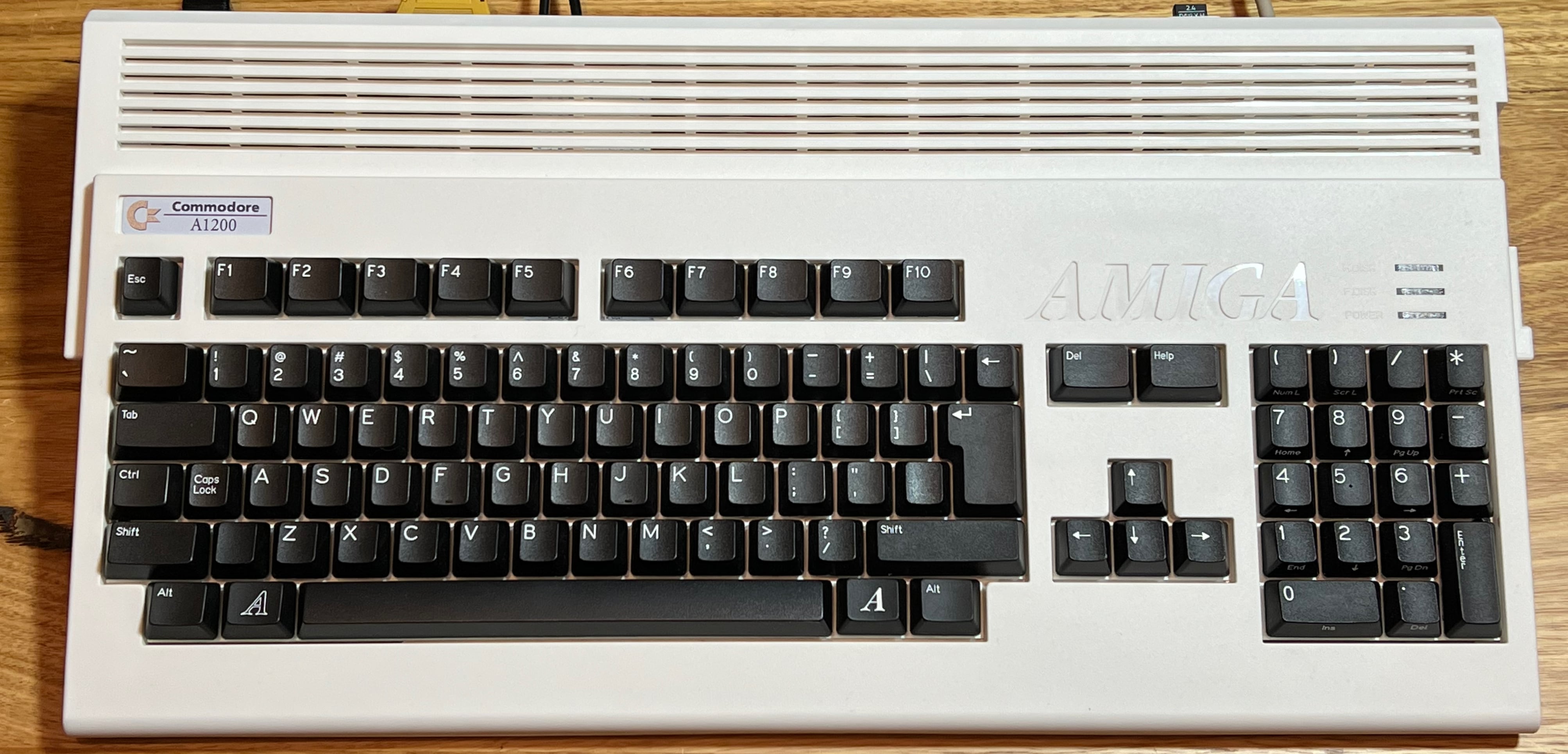
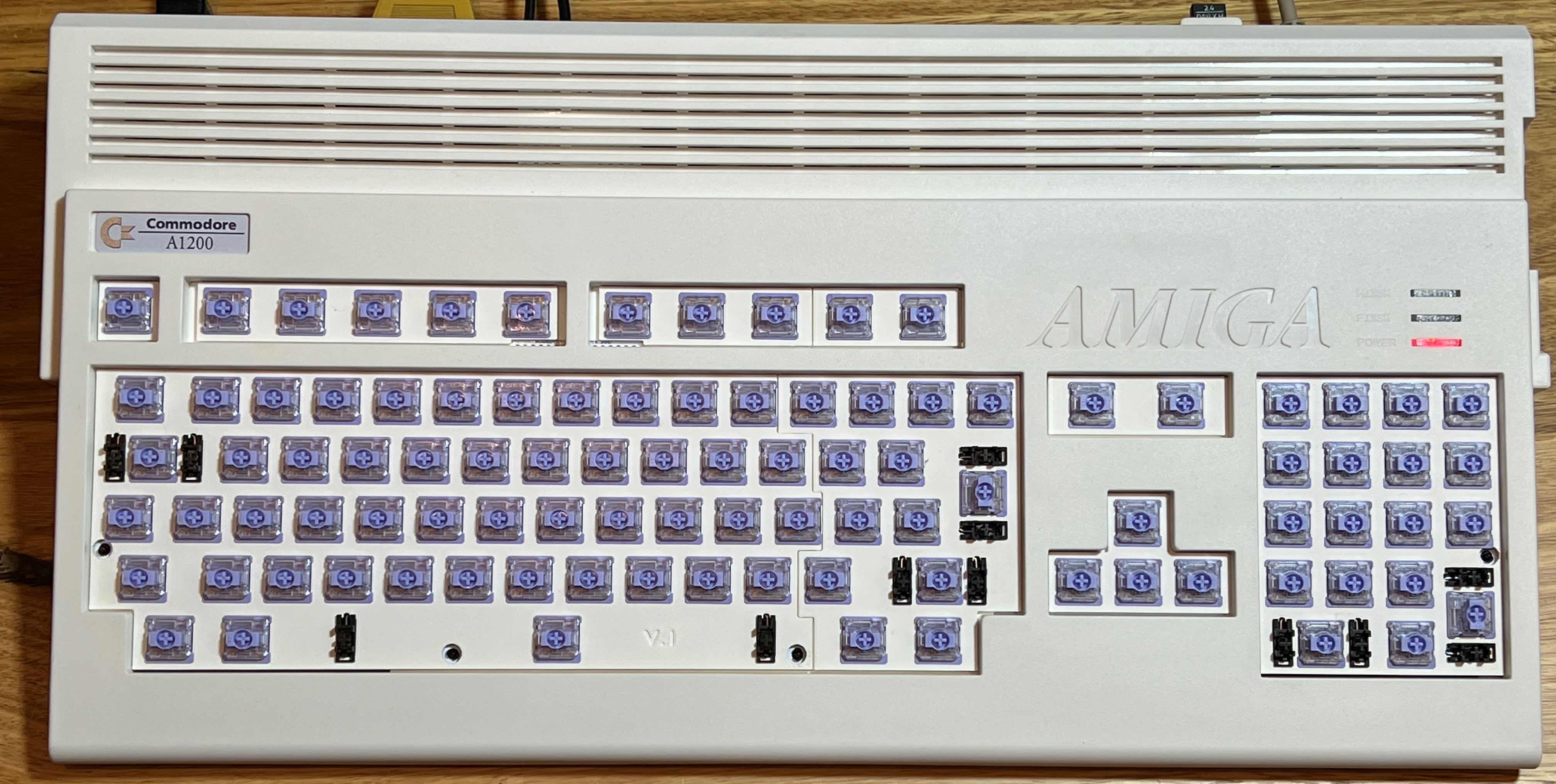
This post is about the result of that work, showing off the new A600 and A1200 keyboards.
Physical construction
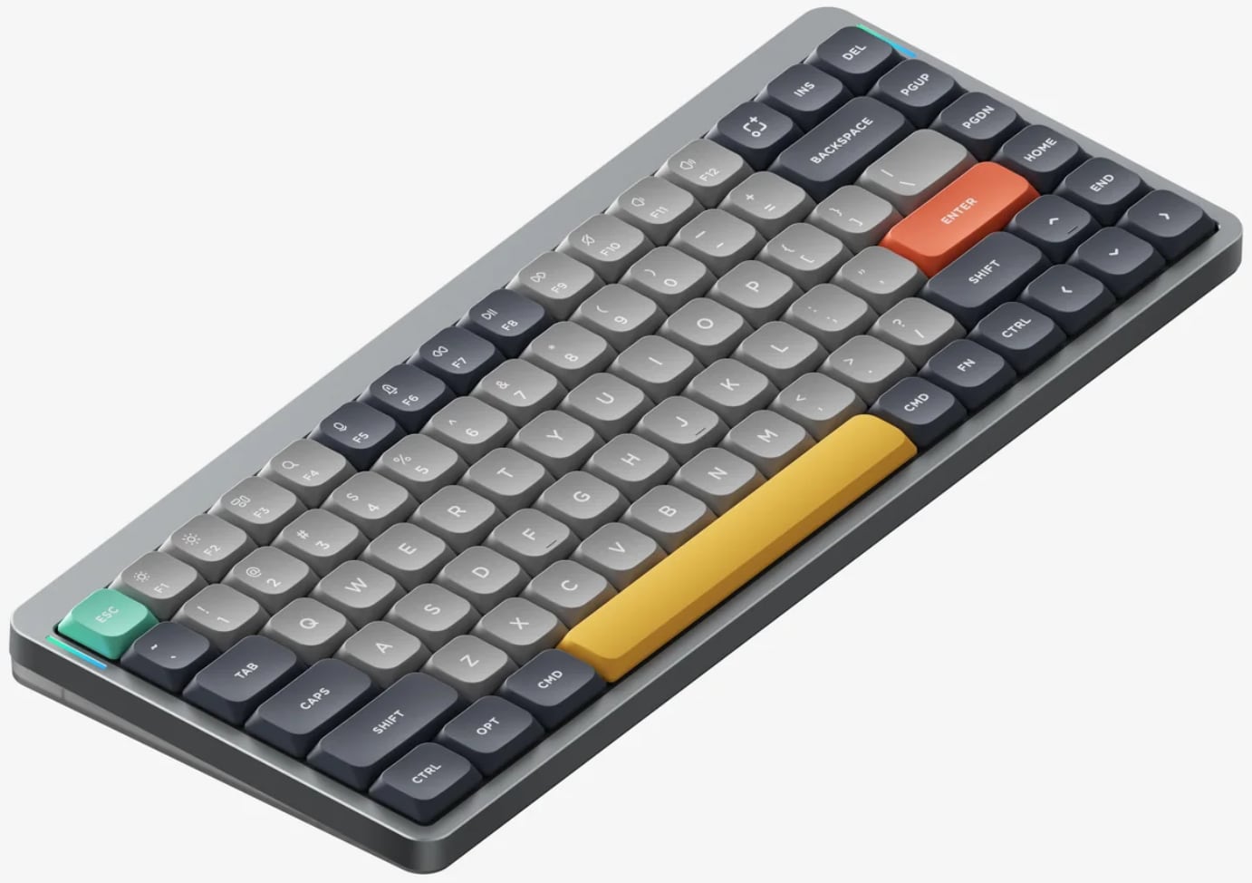
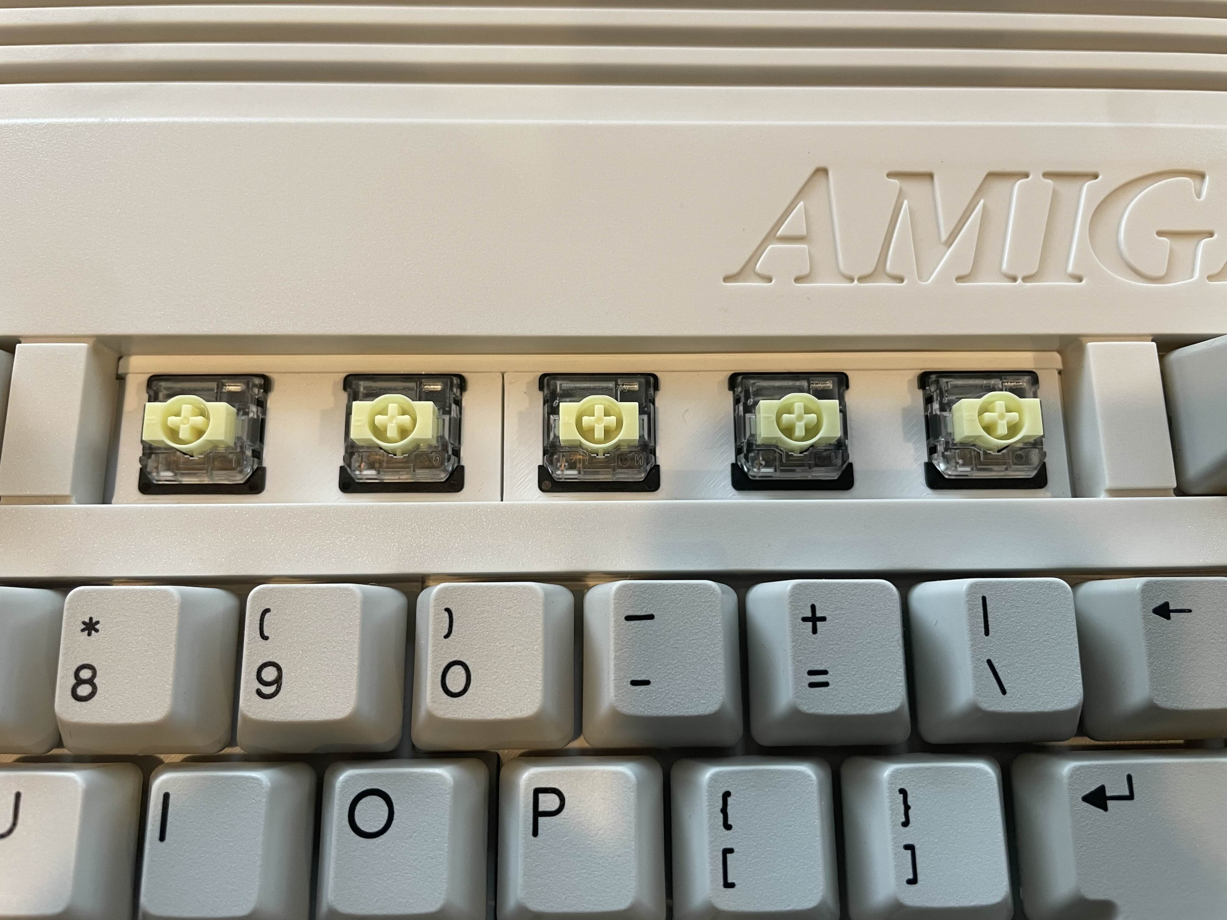
For both keyboards I used the Gateron KS-33. I first tried these in a Nuphy Air 75 V2 which is now my favourite and I use it daily (but the firmware, terrible!). I find the key travel perfect and really like the banana tactile keys, a slightly heavier version of the familiar brown. Red or silver (linear) and blue (clicky) styles are available too. The height of these switches is 8.8mm base-to-top, compared with 15mm for a regular MX.
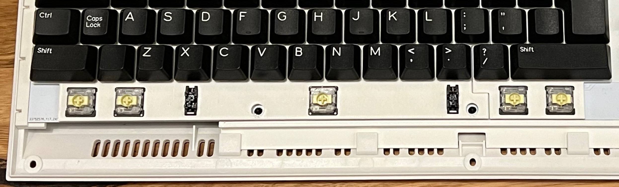
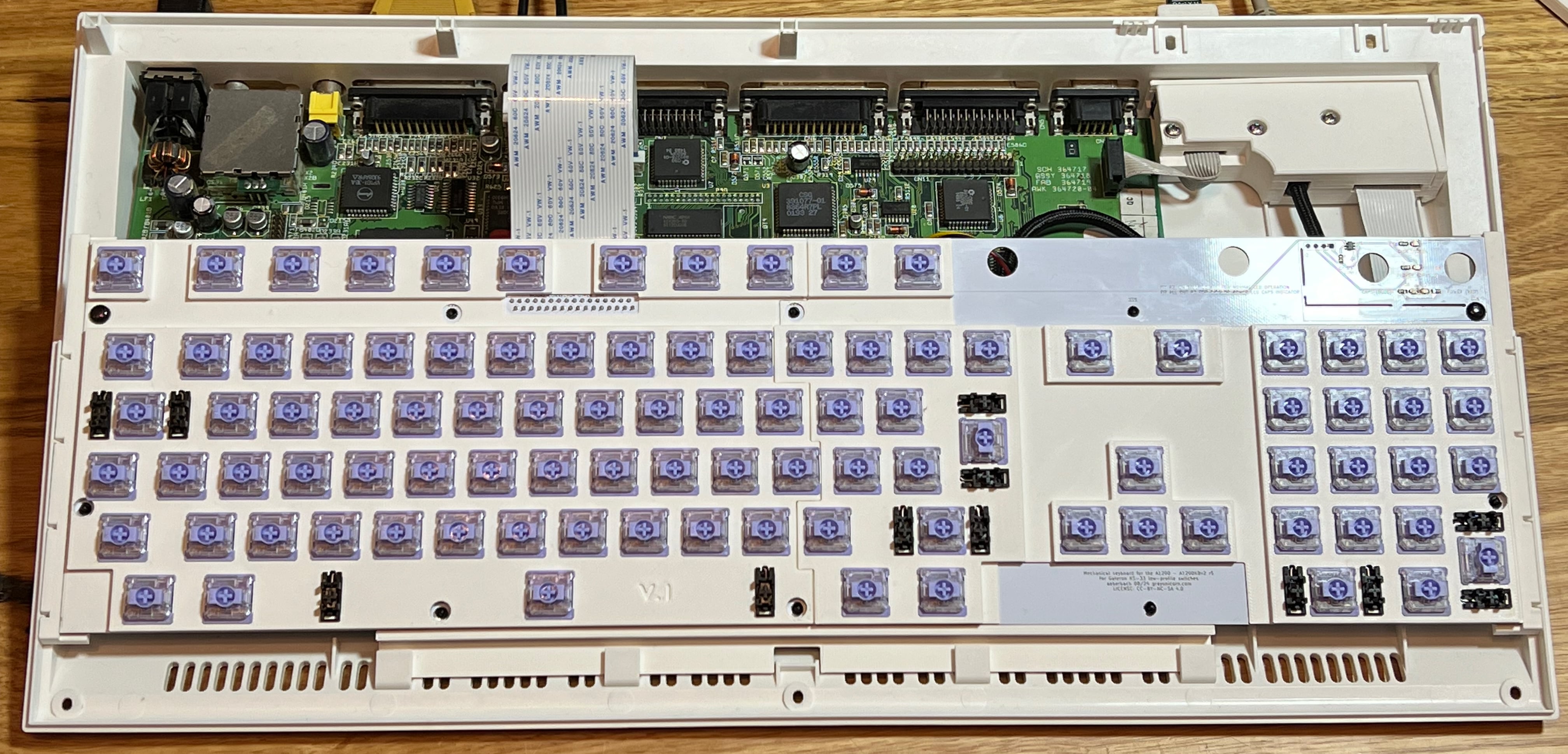
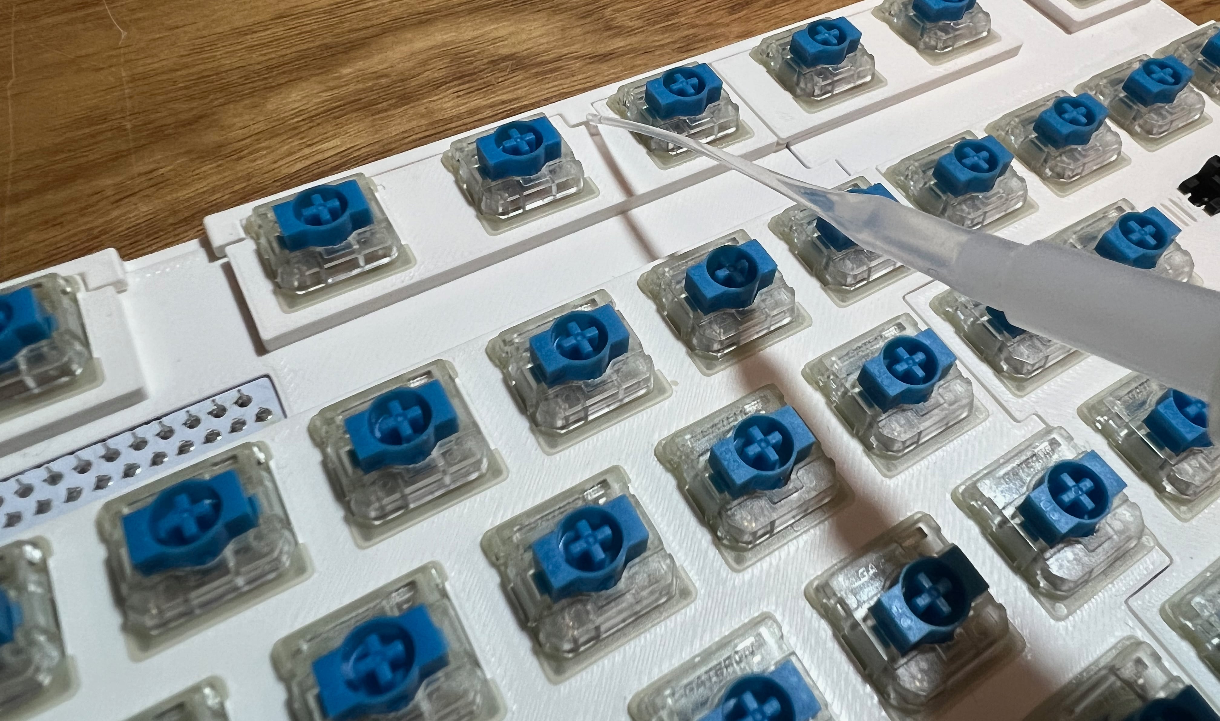
These switches only come in a 3-pin mount, one large central locating pin (also the housing for the internal spring) and two electrical pins. Because they do not have two extra side pins to set the location these would be very hard to mount straight if not using a plate - also because of the stabilizers available a plate is a must. These stabilizers mount level with the switch top, not the PCB. I looked into having a plate made but a simple laser-cut sheet is expensive, and won't work without some material under it providing thickess and room for the stabilizer wires, so if I have to print something may as well print the whole thing? The decision was helped by finding some "Milky White" PLA filament that prints sharp and is a great color match for the A1200 case. Also the availability of an ultra-reliable Prusa MK4 helped.
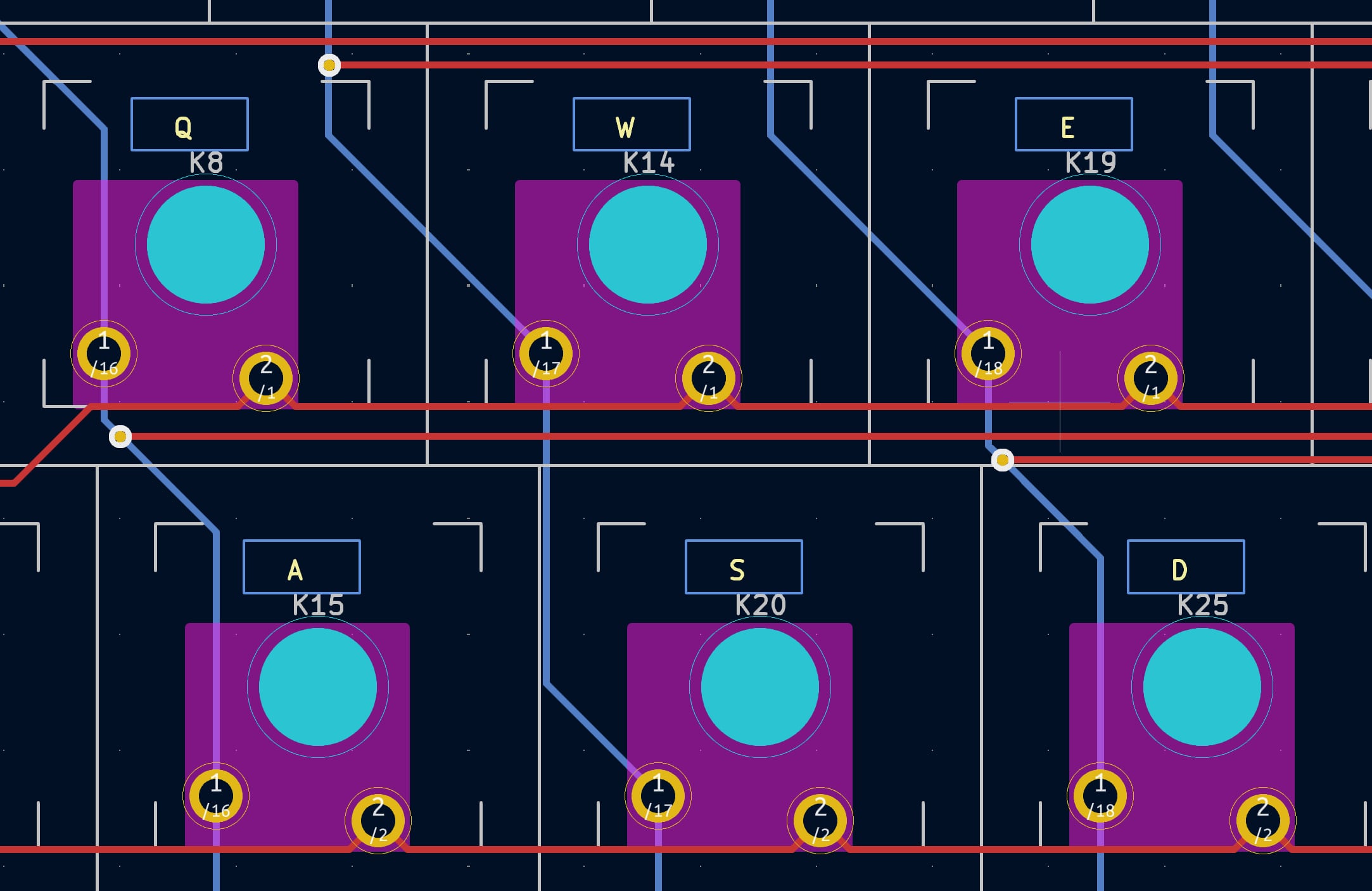
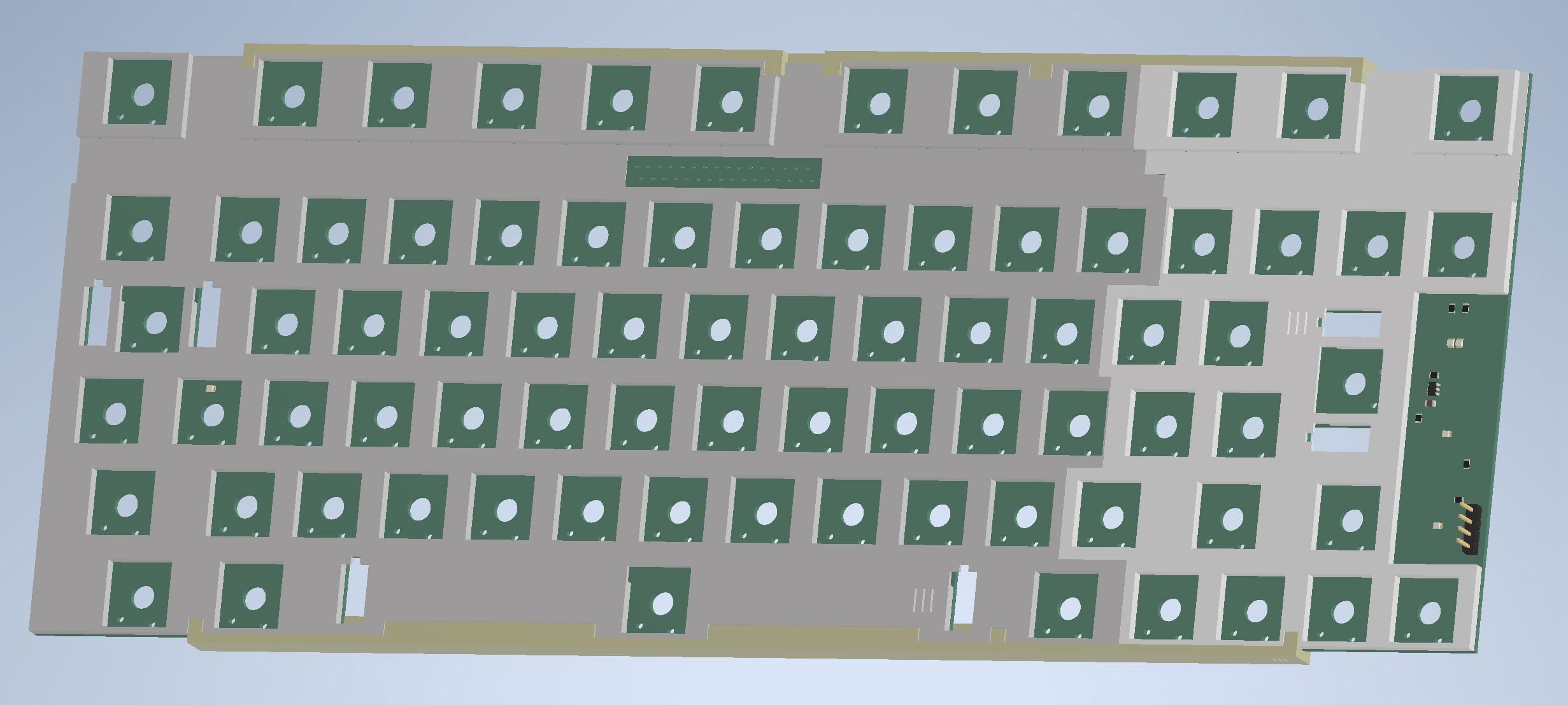
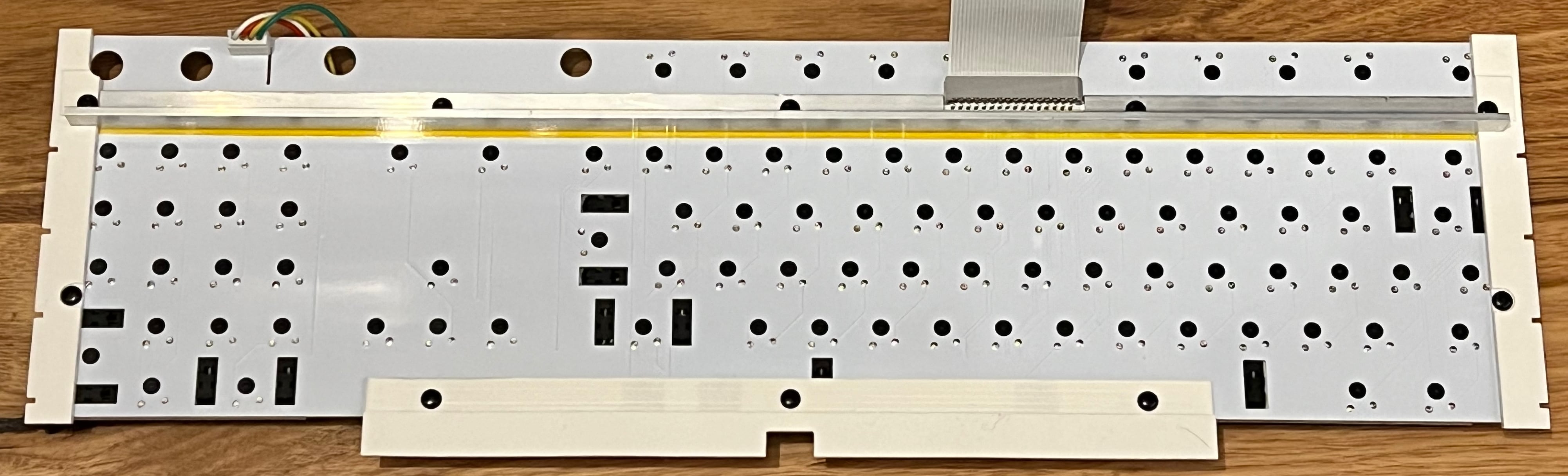
Designing the PCB was a little easier after having done a couple of keyboards already. Position of the keys was already known, and routing the traces again was not hard, made easier by not having those two locating pins on every switch. The connector and FFC ribbon remain the same from the old version.
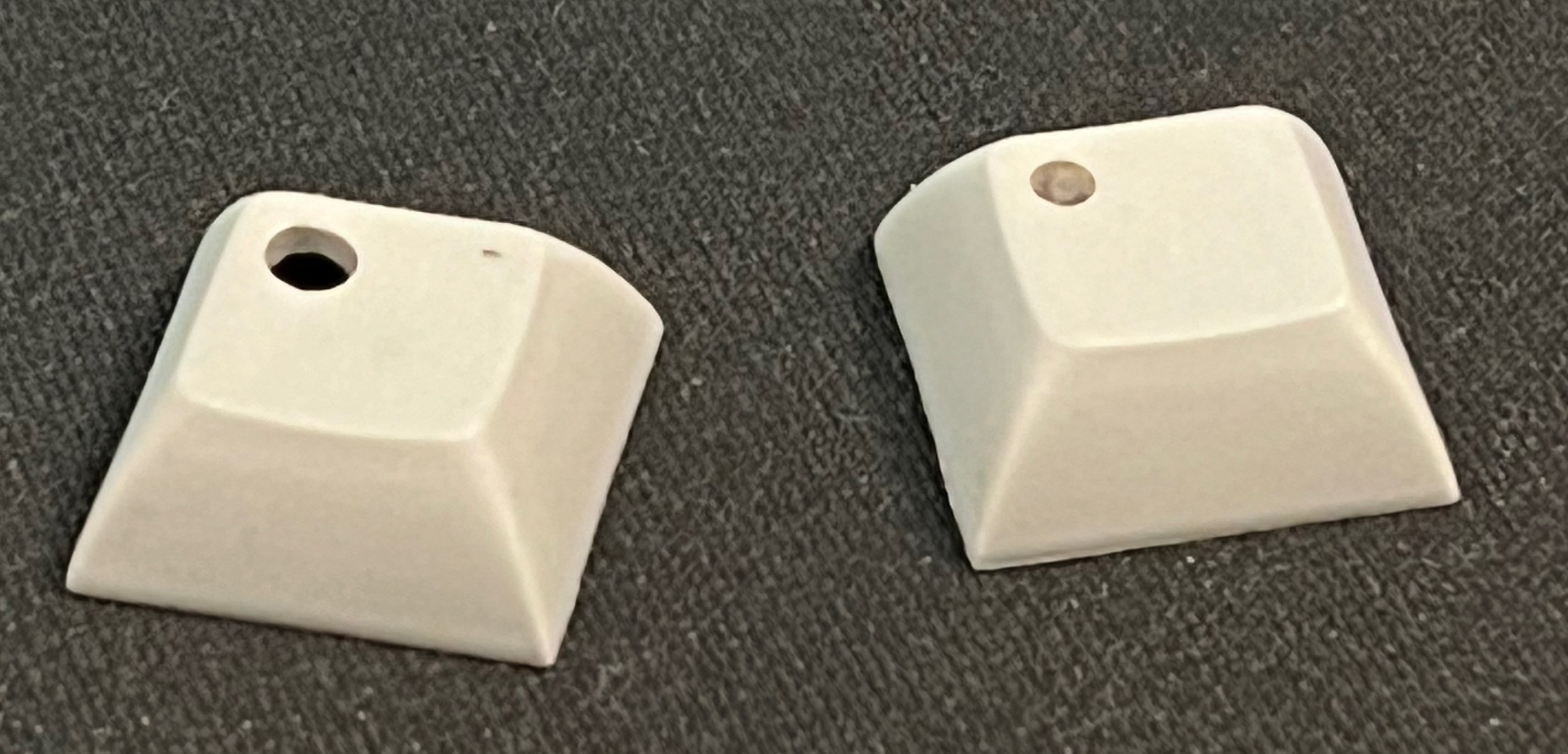
Caps lock was always a problem. I once tried drilling a hole in a Caps Lock key and filling it with clear silicon to make a key with a window but it never really worked well. You just can't buy windowed keys that match the rest of the keys any more. A red glow under the Caps Lock key was visible, but not ideal.
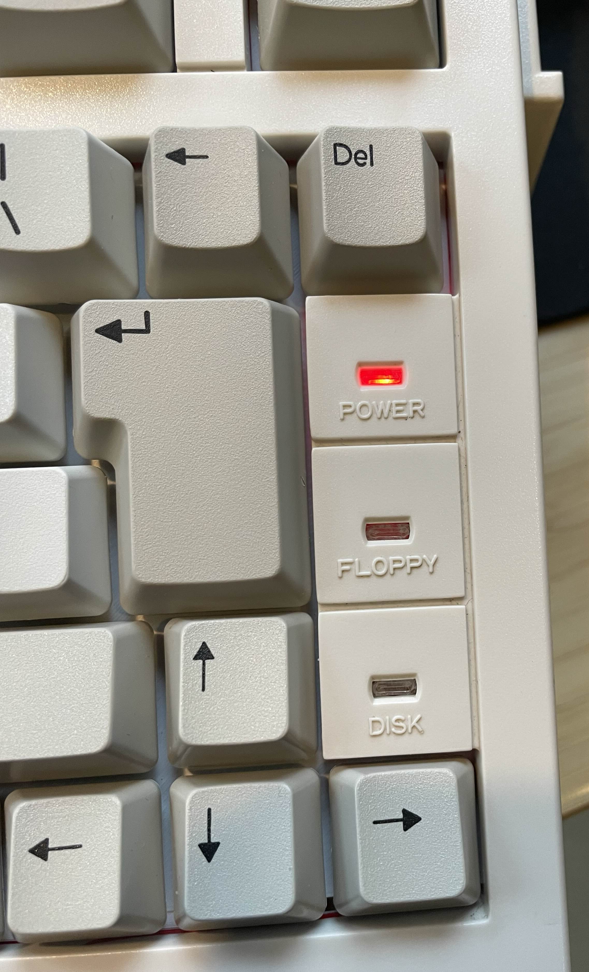
To solve this I looked to a chip I read about recently, a Dual Inverter capable of supplying (or sinking) enough current to light LEDs. The idea is that the output of one inverter is chained to the other. When the input is high the output of the first inverter is low and the second is high. Make the input low and the output of the first inverter is high while the second is low. This means that with LEDs attached to those inverters one will be on at any given time.
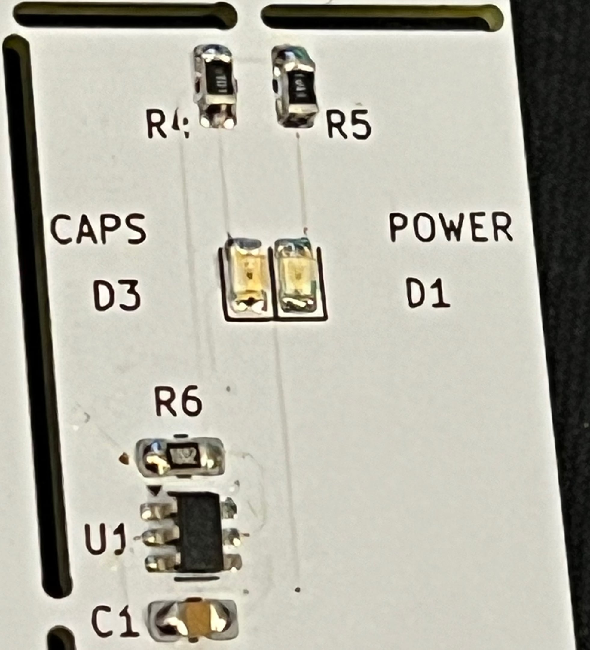
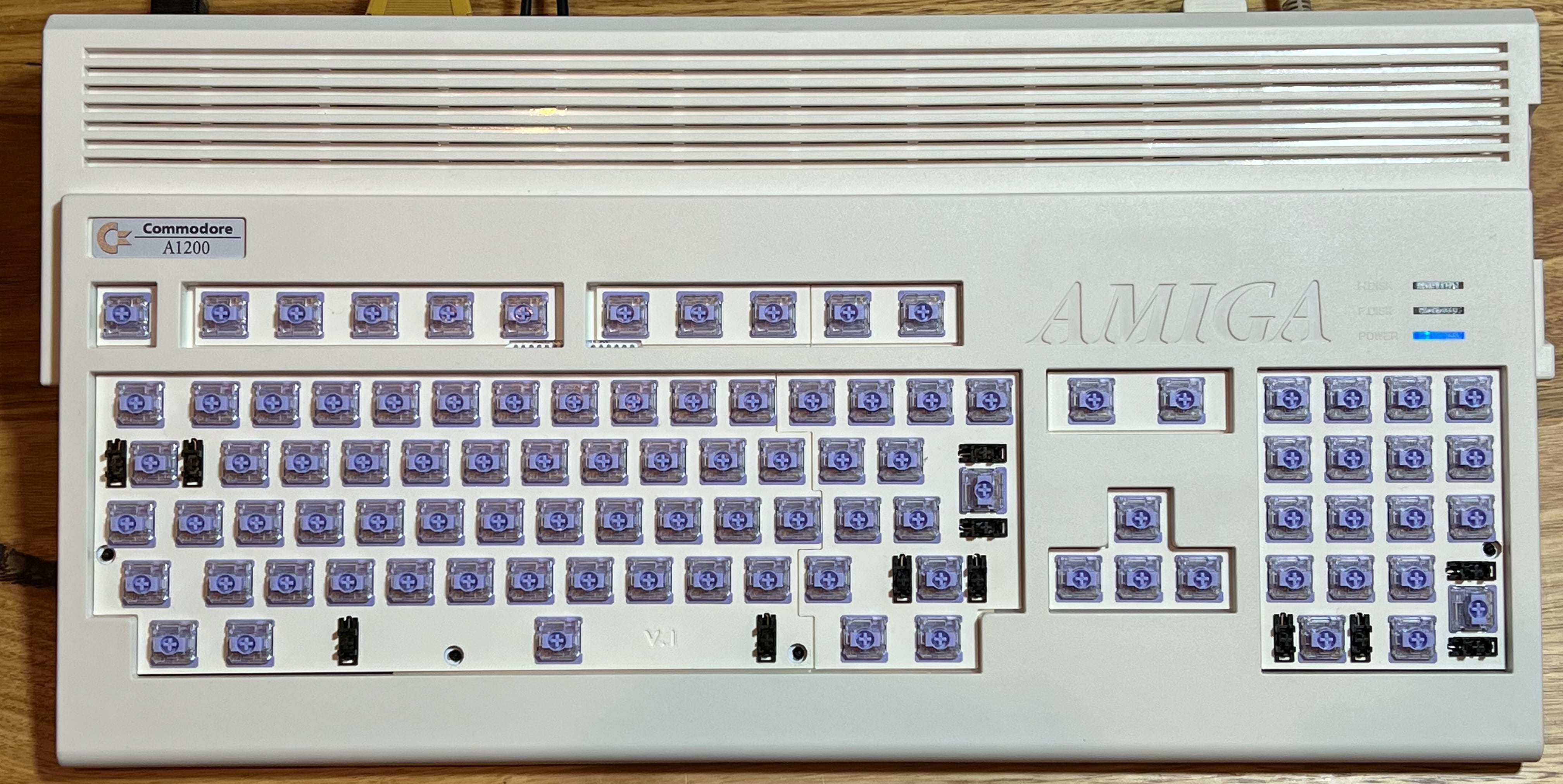
Normally the Amiga shows a red LED when power is on. What I have done is take the Caps Lock signal from the Amiga and use it as the input to the inverter. When off it is high, so the red power LED, cathode connected to the first inverter, is on. When caps lock is on then no current flows through the red LED, but the blue LED, cathode connected to the second inverter, is lit. With these two side by side and visible through the translucent light pipe the effect is of a single lamp changing color. This LED section of the keyboard replaces the separate LED board in the A600 or A1200, and plugs into the same 4- or 5-pin header on the Amiga.
Now when you open the A600 there are two cables to unplug before you can lift the top free, keyboard and LED. In the A1200 there are no cables to unplug. Don't know about you but I have forgotten the LED board many times when taking the lid off the A1200 and have broken the cable once. If you don't want to use this new LED idea the old LED is still there under the Caps Lock key and you can just break out the LED section of the keyboard PCB, it's routed so that it will snap out. If you do want the LED section but no color changing Caps Lock function, load one 0R resistor, leave off the inverter and blue LED parts, and the LEDs all work as normal.
Keyboard Plates
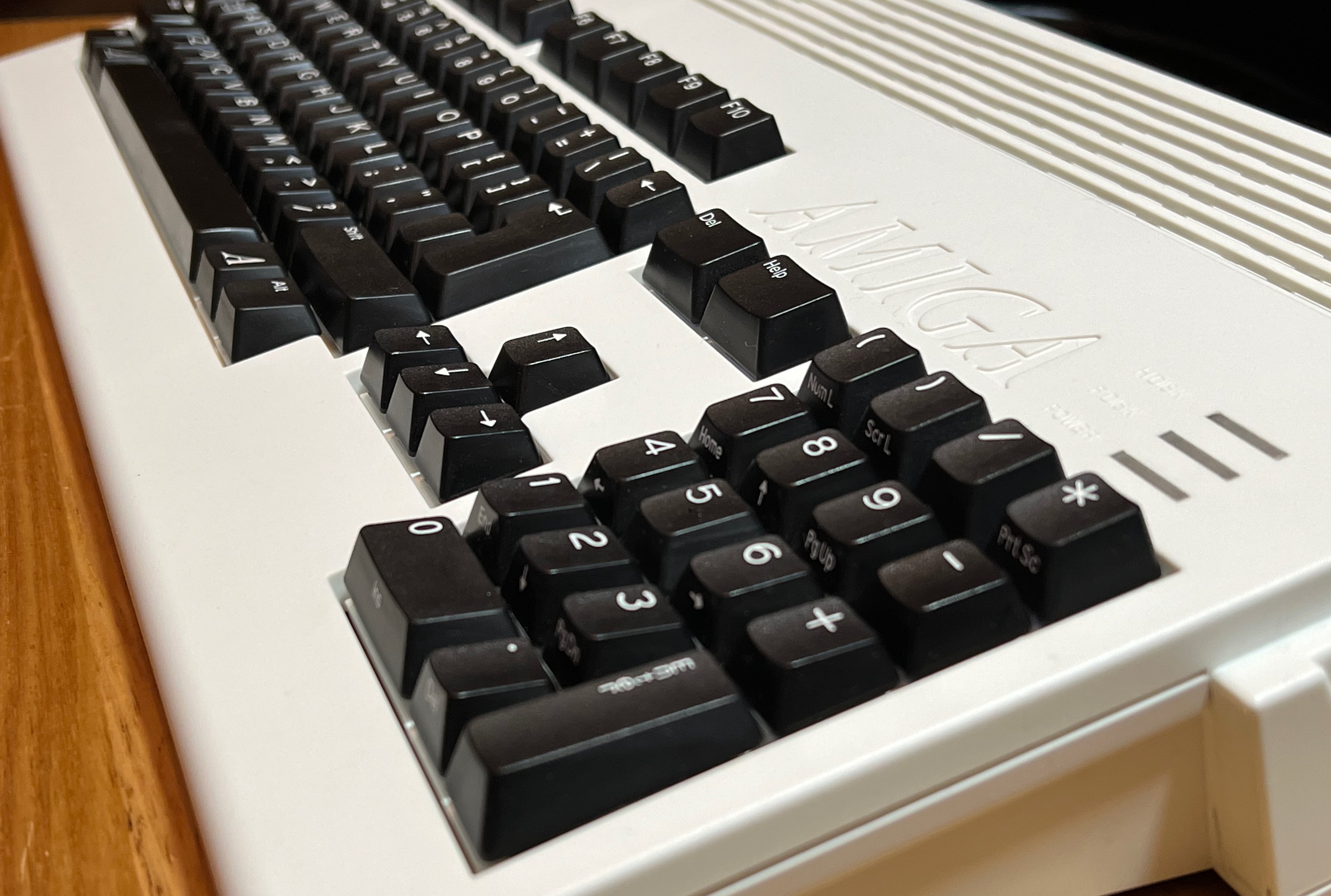
KiCad is an amazing piece of software, not only does it do the work of packages costing thousands it will generate a STEP file for use in 3D CAD software. With the STEP file I was able to make an Autodesk Inventor assembly and create the keyboard plates and mounts. The plates are in two pieces since the widest I can print is around 250mm. Each plate supports the switches and the stabilizers and is held to the PCB by the soldered switches. The stabilizer cuts took some adjusting, initial version (following the manufacturer's drawings) had the keys not springing back up as they should, but after a few tweaks they are smooth.
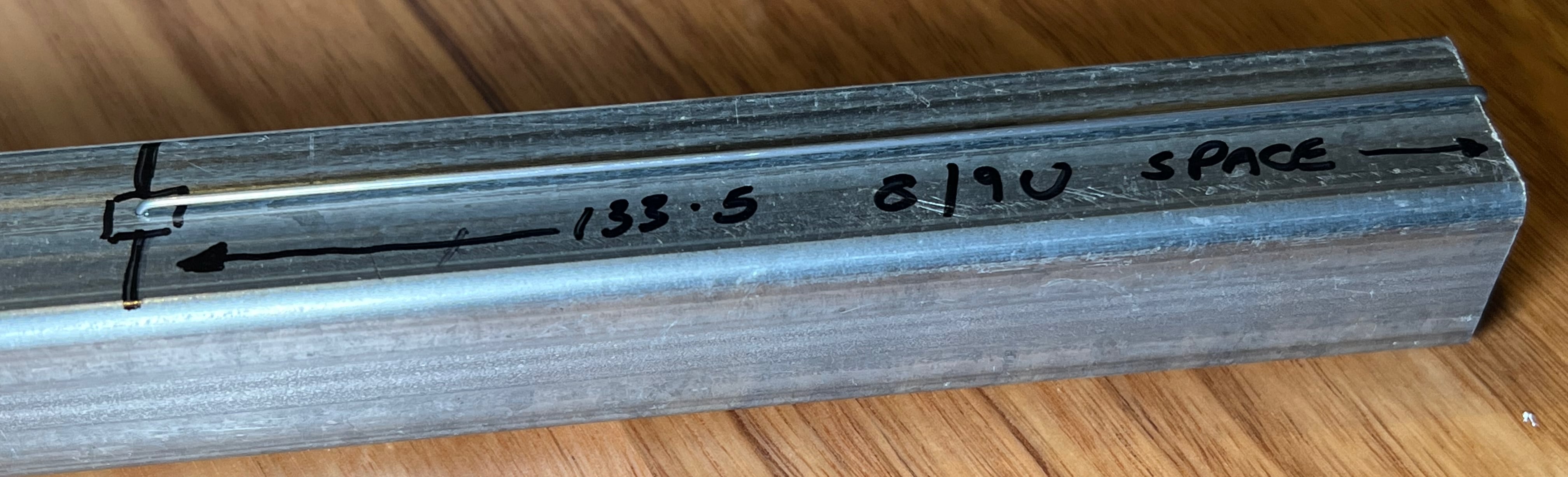
Nobody makes an 8U/9U keyboard stabilizer now of course, and A600 uses an 8U space bar while A1200 uses a 9U. For this I needed to take a 2U stabilizer, discard the wire and bend a new wire using 1.0mm music wire from the hobby store. If this is not accurately bent the space bar will not bounce back up when you depress it, or will feel different when pressed on either side. If you think you will be bending more than one, make a jig. You will probably be bending more than one unless you make the jig though, because by hand it is very unlikely to be right first time! This is a square section of steel with a 1.0mm hole drilled 133.0mm from the edge. You definitely need a centre punch and cutting oil for this. When a wire has one end bent at a right angle and that end is inserted in the hole with the wire laying along the steel bar, bending it over the edge will make a good 133.5mm space bar wire. Not shown is the notch on the other side of the bar that lets me trim the bent ends to a consistent length, also very important.
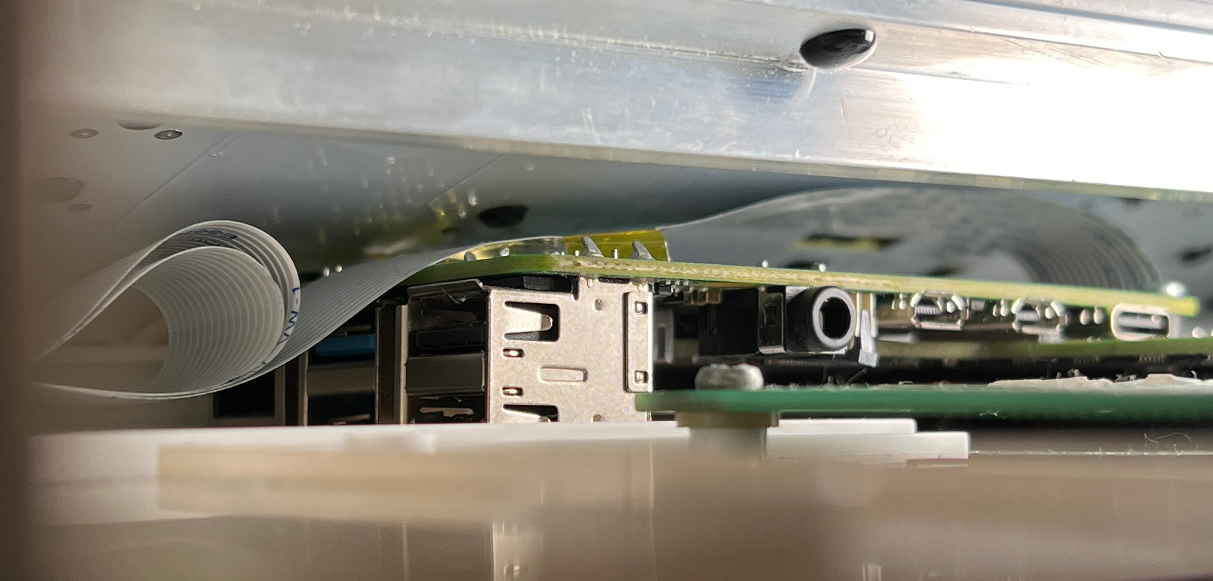
The plates are 3mm thick in places and 0.5mm thick in others. The 3mm sections support key switches, slightly off the PCB, so that less of the switch pins poke through the PCB. Stabilizers are also supported by the plate and they snap in before everything is constructed with the wires hidden from view. The 0.5mm sections tie the 3mm sections together which is important to locate everything relative to the other parts. Where the plate contacts the top of the Amiga case it is in a 0.5mm section. This means the bottom of the keyboard PCB is 1.6mm (PCB) + 0.5mm (plate) down from the bottom of the case - there's a lot more room inside the case as a result. The supporting bar and the FFC connector protrude a bit but they should be well out of the way. My PiStorm32-Lite is installed with room to spare.
Mounting the Keyboard
A1200
For the A1200 there are two kinds of case bottoms, A1200.net and Commodore/Escom. Both have ridges along the side where the keyboard mount sits but they are in different positions, so different versions of the mount are required with the ridge cuts moved to suit. The bottom mount piece is common between both. (There was a mistake in my original mount design: the mounts sat too high so the case did not close exactly.)
To keep the A1200 keyboard from flexing over its 450mm span the plate helps a little bit but an aluminium bar is still required to make it stiff enough. In the old version the keyboard could bounce slightly off the supporting bar - a little bit of double sided tape helped. The new version uses a right-angle extrusion and has five mounting points along the bar so it does not move around at all. The one shown here is slightly rough as it is the first one I made, yellow Kapton tape is under it for insulation.
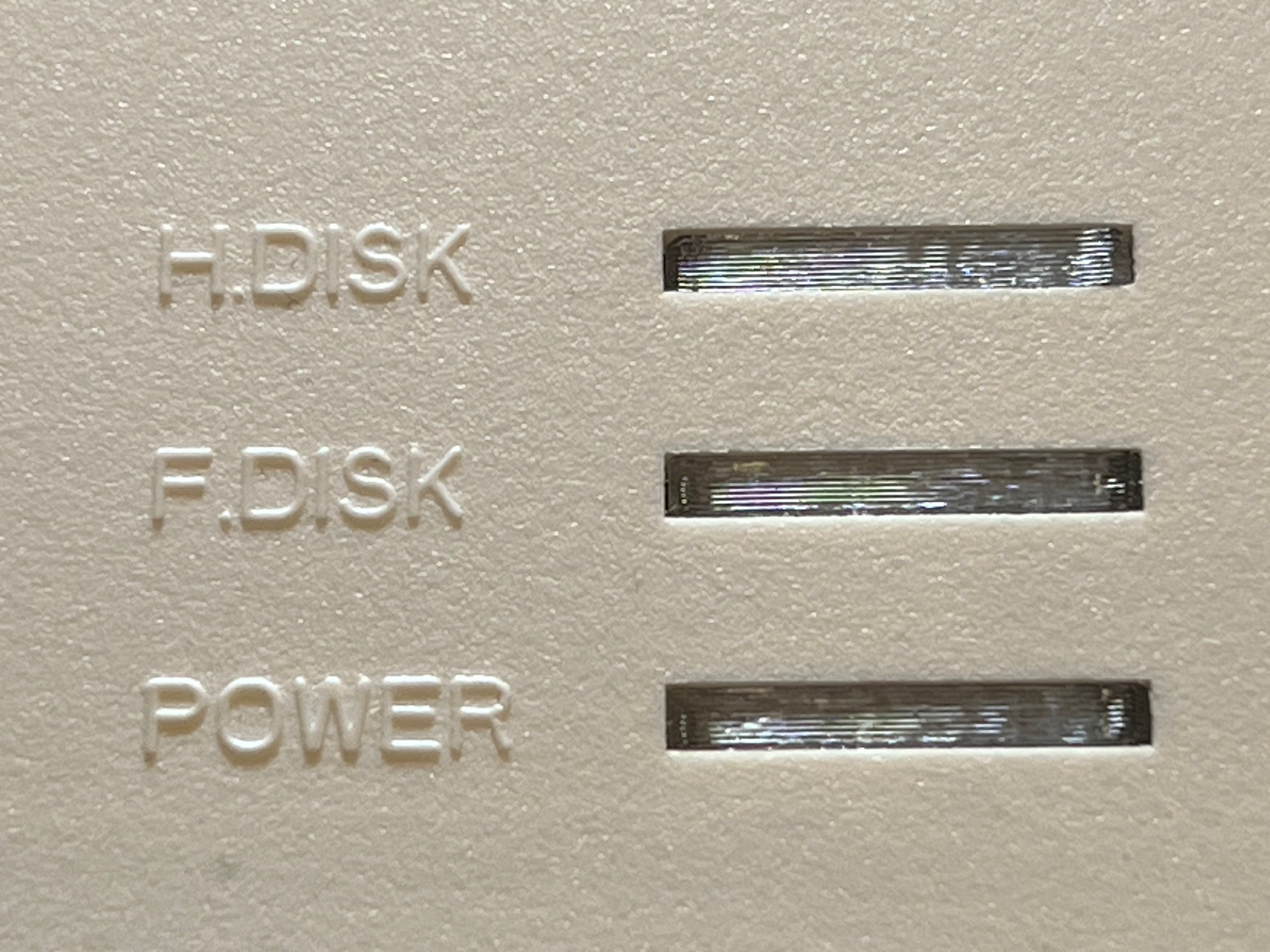
For the A1200 case top the only variation is the width of the light pipes - if you have the one with narrow LED slots you just need to shave off the top bit of the light pipes with a craft knife. It's a much better option that shipping just the narrow option and leaving a gap in everyone else's case. I have printed a light pipe assembly that uses translucent PETG filament and makes the whole thing look very complete.
The entire thing is put together with plastic rivets. I first bought these for another project. They make assembly quicker, they are non-conductive, the are compact, this is a perfect place to use them. M3 bolts and nylock nuts would work as well, if that's what you have.
A600
In the A600 the keyboard mounts between one long claw and two short claws opposing on the top of the case. The design of the plates is such that the top and bottom mount pieces sandwich the PCB and plates and fit between these claws with the top piece locating the keyboard exactly in the width of the case. These interlock, and since they are printed in PLA a very tiny dab of cyanoacrylate glue is enough to keep everything together. Do not use ultra-thin glue here as it will wick through the whole PCB and possibly destroy the entire keyboard. Do not use too much!
Fitting the keyboard is exactly like the original - flexing the top of the case slightly makes it easy to put the keyboard in its place. Once it is pushed in under the claws and you can see that the top notch is sitting between the F key apertures it's in.
Light pipes in the A600 are much simpler, just small pieces of translucent PETG to push into the LED holes.
Cables
In the original design the FFC cable and Right-angled FFC connector were only available from one place, Mouser Electronics. Only a 32-way 178mm cable could be bought, also the only FFC connector available was 32-way. 178mm is a bit too long but the next shortest was far too short, and there are too many conductors as the A1200 requires 31 and the A600 requires 30. I got around this by trimming either one or two conductors from the Amiga side of the cable and just tucking in the extra length where it would fit.
This keyboard design is no different - 32-way right-angle connector, 32-way cable. Using the white locking connector as the Amiga mainboards use is an option but more expensive and fairly tall. Also if the perfect cable isn't available that means you have to trim conductors from both ends. I am making inquiries with various suppliers in China to see if I can get 31- and 30-way cable systems but if the quality isn't as good as the Mouser parts it won't be a great option. The last thing anyone wants is a dodgy ribbon cable, a problem that the original keyboards often had when the membranes wore out.
Where do I Get One?
I'm going to produce one run of keyboards, you can order them from me on Amibay.
When that one set of orders is all done both repos will be made available on github including all design files, under a CC BY-NC-SA license. Free for anyone to download and use, not for commercial sale.